
Seal Strength Test: Peel Force, Fixtures & Failure Modes
How ASTM F88 seal strength testing controls tail support angle, peel force limits, units, and failure modes across flexible and foil-sealed packaging.
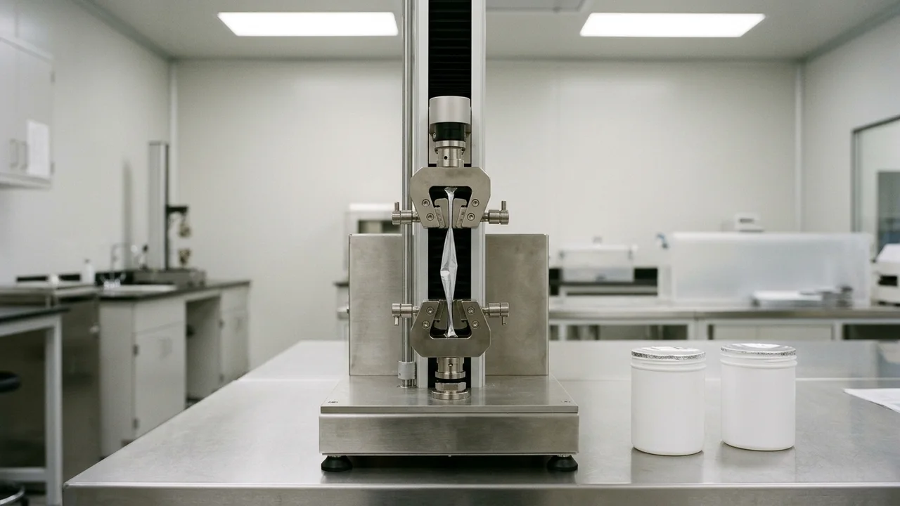
A seal strength test under ASTM F88/F88M-23 measures the mechanical force required to peel apart a cut strip containing a heat seal and classifies how the specimen fails. Because bending stiffness in the unsealed tails adds extra force to the load reading, locking in one tail-support geometry—unsupported (Technique A), 90° hand-supported (Technique B), or 180° alignment-plate supported (Technique C)—is essential before comparing maximum or average peel strength against minimum closure and maximum opening limits.
What is a peel strength test?
A peel strength test—often called a seal peel test or, when both tails hang free, a T-peel test—measures the separation force between two bonded packaging layers along a localized strip. Under ASTM F88, those two layers may be flexible-to-flexible films (such as pouch webs or Tyvek-to-film headers) or a flexible barrier web sealed to a rigid or semi-rigid flange.
For containers closed with foil-laminate liners, peel force is one piece of a broader verification program on the seal integrity testing hub. Strip peel strength differs from whole-package methods on three clear boundaries:
- Whole-lid container peel (ASTM F2824): Rather than cutting narrow strips, ASTM F2824 pulls an entire flexible lid, cover, or membrane off a round rigid or semi-rigid container—using a 45° pull angle by default unless another validated angle is documented—and logs both continuous and peak separation forces.
- Whole-package burst, creep, and leak checks (Heat sealer methods overview): A strip can achieve acceptable peel strength and still leak through an unbonded pinhole or narrow channel. Labs pair ASTM F88 with internal-pressure burst and creep tests (ASTM F1140 and ASTM F2054, where creep holds roughly 80% of minimum burst pressure), visual seal inspection (ASTM F1886), dye penetration (ASTM F1929), bubble emission (ASTM F2096), or vacuum dye tests (ASTM D3078).
- Hot-tack strength (ASTM F1921): ASTM F88 measures cooled, conditioned seals; molten bond strength immediately after sealing jaws open requires a dedicated hot-tack method.
In regulated cap-sealing lines, tamper-evident 21 CFR 211.132 OTC drug packaging requires a barrier to entry that leaves visible evidence if breached or missing. As Wikipedia’s induction sealing summary notes regarding FDA Compliance Policy Guide CPG 7132a.17, heat-induction container-mouth inner seals are expected to tear or leave visible residue on opening rather than peeling away cleanly for reapplication. Tracking foil peel-off strength monitors weld consistency and helps catch overheating before polymer seal layers degrade weeks after production, connecting directly to cap liner selection and induction sealing machines.
What is ASTM F88 in seal strength testing, and why do tail support angles change the result?
ASTM F88 specifies a strip-based mechanical separation test for flexible barrier seals that captures both bond force and failure mode for process validation, capability studies, and routine lot release. Its most consequential methodological warning is simple: part of the force recorded by the load cell comes from bending the specimen tails rather than breaking the seal bond itself.

To control that bending component, ASTM F88 defines three tail-support configurations, and Note 5 adds that tail movement or flipping during the pull alters measured force and must be recorded with the results:
| Method or Technique | Tail Configuration | Best Fit | Bending & Operator Sensitivity |
|---|---|---|---|
| Technique A (Unsupported) | Both tails clamped in opposing grips; unpeeled seal hangs free in a T-peel | Flexible-to-flexible pouches of similar stiffness; automated QC | Eliminates hand force, though stiff or mismatched webs can rotate or flip mid-peel |
| Technique B (Supported 90° By Hand) | Opposing grips clamp tails; operator loosely supports the unpeeled tail at 90° | Flexible webs that swing or flip excessively under Technique A | ASTM F88 Note 4 warns gripping or lateral hand push skews readings; harder to reproduce across labs |
| Technique C (Supported 180°) | Stiffer tail clamped flat against a rigid alignment plate; flexible leg folded 180° over the seal | Foil lidding on trays, thick laminates, or mismatched stiffness webs | Most repeatable angle; reads differently from T-peel and depends on which tail sits on the plate |
| ASTM F2824 (Whole Lid) | Entire lid separated from a round rigid or semi-rigid container at 45° | Cup, bowl, or tub lids where whole-perimeter continuity matters | Tests full perimeter rather than a cut strip; not interchangeable with ASTM F88 |
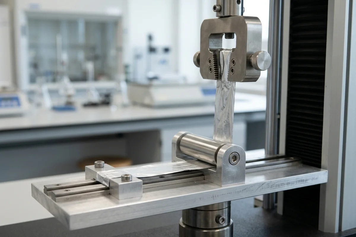
Controlled round-robin data underscores why laboratories must never mix techniques or swap which substrate enters the backing plate. In the Sterilization Packaging Manufacturers Council (SPMC) Interlaboratory Study—three independent round robins across six laboratories testing 30 peelable seals per technique—Series B tested uncoated 1073B Tyvek sealed to PET/LDPE film at 12 in/min across 90° supported, unsupported, 180° supported, and reverse-direction gripping (bending the stiffer web rather than supporting it on the backing plate). Series C compared 3 mil HDPE film against stiffer 5 mil foil composite. Since its three-page 1968 edition, ASTM F88/F88M-23 has expanded to 20 pages with annexes covering strip width, separation speed effects, thermoformed tray holding jigs, and ASTM F3263 validation guidance for fixtures and grip assignment.
How does the ASTM F88 seal strength test procedure work?
A repeatable seal peel test depends on sample conditioning, clean perpendicular strip geometry, centered slack-free clamping, and a steady crosshead speed across all seal sides. Follow this sequence in the laboratory:
- Condition the packages before cutting: Where required, condition whole sealed packages in a standard laboratory atmosphere of 23 °C and 50% relative humidity per ASTM E171. Keystone Compliance notes conditioning durations can reach 40 hours, which stabilizes post-seal polymer crystallization and normalizes humidity-sensitive paper or Tyvek webs. Whole packages undergo any sterilization cycles or ASTM F1980 accelerated aging before strips are cut.
- Cut parallel, nick-free strips perpendicular to the seal: Cut strips with a twin-blade precision cutter or steel rule die rather than scissors, which nick edges and trigger premature film tearing. Standard strip widths are 25 mm, 15 mm, or 25.4 mm (1.00 in), with tails around 75 mm long plus the seal width so jaws clamp without touching the weld. Cutting accuracy directly affects calculated stress: Universal Grip Company points out that a 24 mm strip divided by a nominal 25 mm width understates seal strength by 4%.
- Sample every seal location separately: On a four-sided pouch or lidded container, cut strips from each distinct seal zone—left, right, top, chevron, factory, and closure seals—and keep each data set separate rather than pooling straight seals with corner or overlap areas. Test at least five strips per location for comparative checks, and 10 to 15 peel specimens per condition where ISO 11607 IQ/OQ/PQ validation protocols specify higher statistical confidence.
- Clamp with smooth jaws and center the seam: Mount the stiffer or package-side tail in the designated upper or backing-plate grip, center the seal line midway between and perpendicular to the jaw faces, and leave light slack before zeroing the load cell so the seal starts unloaded. Clip pneumatic airlines or sensor cables to the moving crosshead so hose drag does not offset low-newton readings.
- Pull at a constant crosshead speed of 200 to 300 mm/min: ASTM F88 specifies a constant grip separation rate of 200 to 300 mm/min (8 to 12 in/min). Many North American labs standardize on 250 mm/min (10 in/min) or 300 mm/min (12 in/min), while laboratories dual-certifying to EN 868-5 set 200 mm/min on 15 mm strips and report against each standard independently.
- Log every variable in the test report: Record the ASTM F88 edition, Technique A/B/C, material and seal location, strip width and cutting method, number of tested and discarded strips with reasons, conditioning or aging state, test speed and initial jaw separation, peak and average force per width, any tail flipping, and the failure mode of each individual strip.
What unit is seal strength reported in, and how are lower and upper limits set?
Seal strength is normalized by strip width and reported as N/25 mm, N/15 mm, or lbf/in (some labs also convert to N/m). Under Clause 1.6 of ASTM F88, SI and inch-pound units are treated independently and are not mixed within a single compliance specification. Where engineering teams convert reference values across regions, Universal Grip Company gives the exact width equivalencies:
- 1 lbf/in = 4.378 N/25 mm = 2.627 N/15 mm
- 1.5 N/15 mm (the EN 868-5 minimum for steam-sterilized pouches) = 2.5 N/25 mm or 0.57 lbf/in
- 1.2 N/15 mm (the EN 868-5 minimum for non-steam sterilization) = 2.0 N/25 mm or 0.46 lbf/in
Do not mix 15 mm and 25 mm strips within one test study even after dividing by width, because edge effects along slit film margins do not scale linearly.
Peak force, averaging windows, and the seal strength window
ASTM F88 designates maximum seal strength (peak separation force divided by strip width) as the primary metric and recommends also reporting average seal strength over the peel plateau where useful. Because the standard does not fix one averaging boundary, protocols state the exact evaluation span—commonly excluding start-up spikes and end drop-offs by averaging the middle 10% to 90% of peel travel. If a trace plunges abruptly toward zero mid-peel, inspect the specimen for a channel or unbonded skip rather than smoothing the dip into an average.
Acceptance limits form a two-sided process window tailored to the package design rather than a single universal target:
- Lower limit: Guarantees closure survival through sterilization, distribution vibration, and handling. Boulder Package Testing cites typical peelable sterile medical pouches running roughly 1.0 to 4.0 lbf/in (with broader industry peelable designs commonly falling around 1 to 5 lbf/in, or roughly 4 to 22 N/25 mm), anchored above EN 868-5 floors where applicable.
- Upper limit: Applies specifically to peelable closures so clinicians or end users can open the package cleanly without shredding film, pulling paper or Tyvek fibers, or spilling contents.
How do you classify ASTM F88 failure modes?
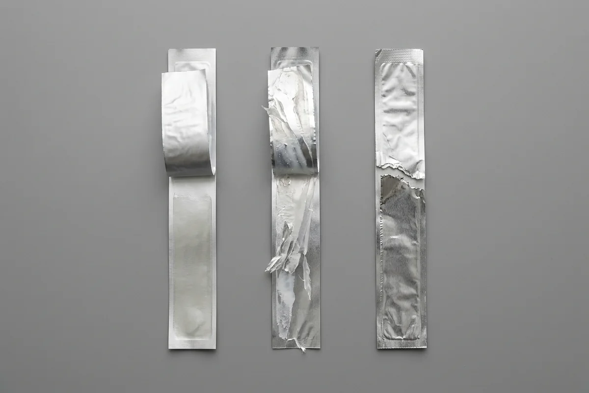
Recording force without the specimen failure mode leaves ASTM F88 data incomplete: a strip that tears the outer web at 4 lbf/in does not behave like a seal that peels cleanly interface-to-interface at 4 lbf/in. Inspect every separated specimen and classify it into the standard modes:
| Failure Mode | Visual Evidence on Strip | What the Result Measures | Validity & Process Meaning |
|---|---|---|---|
| Adhesive (peel) failure | Two layers separate cleanly at the original seal interface | True interfacial peel strength | Target mode for peelable lids, pouches, and lidding films |
| Cohesive failure | Sealant splits internally, leaving polymer residue on both faces | Internal cohesion of the peelable sealant layer | Strong bond; intended behavior in specific peel-coat formulations |
| Delamination | Multi-layer laminate splits between internal plies near or inside the seal | Inter-ply laminate adhesion rather than the heat seal | Flags weak foil-to-film lamination or overly aggressive heat-seal temperature |
| Material tear or break at seal edge | Substrate snaps or tears right along the seal boundary before peeling | Tensile/tear strength of the film or foil web | Expected on permanent lock-up seals; signals over-sealing on peelable packages |
| Break at grip or away from seal | Strip tears inside the jaw line or in the unsealed leg | Clamping nick or edge-cut flaw | Invalid specimen; discard with documented reason and adjust jaw pressure or cutter |
| Elongation | Long upward ramp on force trace before seal separation or break | Strip stretching mixed into peel work | Check Technique C backing support and distinguish web stretch from bond strength |
What machine measures seal strength, and what affects tester price?
Compliant ASTM F88 peel testing requires a motorized single-column or dual-column tensile tester capable of holding a constant 200 to 300 mm/min crosshead speed under load; manual hand-cranked testers serve only for informal shop-floor checks because hand cranking cannot hold a regulated separation rate. Equipment investment scales primarily across five hardware specifications rather than frame brand alone:
- Load cell capacity and low-force accuracy: A 1 to 10 lbf/in seal on a 25 mm strip generates only 4 to 45 N (weak peelable seals can fall under 5 N). Using an oversized 5 kN cell puts a 5 N peel at 0.1% of rated capacity, burying the signal in noise. Mark-10 demonstrates why capacity must match load: a 50 lbF force gauge rated at ±0.1% full scale carries a fixed error of ±0.05 lbF—which equals ±0.17% of reading at 30.00 lbF, but balloons to ±5% of reading at 1.00 lbF. Selecting a dedicated 50 N to 500 N load cell improves repeatability far more than upgrading frame tonnage.
- Frame column geometry and environmental options: Compact single-column stands (for instance, benchtop frames in the 100 lbF to 2.5 kN class) handle standard 200–300 mm/min ambient strip peels cleanly, whereas wider dual-column frames (5 kN to 10 kN class) add column clearance and budget for temperature chambers when hot-fill, retort, or cold-chain specifications require testing at service temperatures rather than ambient lab conditions.
- Grip type and jaw faces: Smooth rubber-faced pneumatic grips (25 mm to 50 mm wide to clamp 15 mm and 25 mm strips evenly) use regulated air pressure and a foot pedal so operators keep both hands free to align the seam. Screw-action vise grips cut hardware cost for lower-volume labs and easily clamp a Technique C rigid alignment plate, while self-tightening roller grips hold heavy Tyvek or paper without compressed air (though line contact can nick very thin films). Avoid serrated metal faces on thin webs to stop jaw-edge breaks.
- Sampling rate and control software: Peelable seals separate in rapid stick-slip micro-events, so capture electronics should sample at 100 Hz or faster (instruments such as Mark-10 sample internally up to 14,000 Hz while streaming 25–50 Hz) to resolve true peak force, compute custom averaging windows such as 10% to 90%, log failure modes, and export SPC statistics.
- Do not buy an extensometer for F88: Because seal strength divides force by width against crosshead travel rather than measuring material strain, a contact or video extensometer adds cost without improving ASTM F88 data.
Specimen gripping and failure mode checklist
Use this checklist before starting an ASTM F88 run and while logging each specimen on the test bench:
- Method and width locked: Confirm Technique (A, B, or C), strip width (15 mm, 25 mm, or 25.4 mm / 1.00 in), crosshead speed (200 to 300 mm/min), and averaging window (such as 10% to 90%) match the written protocol.
- Conditioning and delay verified: Confirm samples completed post-seal dwell, any sterilization or aging cycles, and conditioning at 23 °C / 50% RH (up to 40 hours where specified) before cutting strips.
- Strip edges inspected: Cut strips perpendicular to the seal with a twin-blade cutter or sharp die; measure true width and discard any specimen with nicks, wrinkles, or visible seal channels.
- Load cell and grips matched: Verify load-cell capacity fits expected peel loads (50–500 N class for most peelable barriers), jaws are 25–50 mm smooth rubber-faced, and hoses/cables are clipped to the crosshead.
- Alignment and zero check: Center the seal midway and perpendicular to the pull axis (or flat against the Technique C plate for 180° runs), leave slight slack so the seam starts unloaded, and zero the force channel.
- Mode and anomalies recorded: Document maximum and average force per unit width alongside exact failure mode (adhesive peel, cohesive split, delamination, edge material tear, or invalid grip break) and flag any tail flipping or sudden mid-peel channel drops for separate investigation.
Sources
- ASTM International — ASTM F88/F88M-23 Standard Test Method for Seal Strength of Flexible Barrier Materials
- ASTM International — ASTM F2824-10R20 Mechanical Seal Strength Testing for Round Cups and Bowl Containers
- U.S. Food and Drug Administration / eCFR — 21 CFR 211.132 Tamper-evident packaging requirements for OTC human drug products
- Wikipedia — Induction sealing
- Wikipedia — Heat sealer
- Universal Grip Company — ASTM F88 Seal Strength Test Complete Guide and Fixtures
- Sterilization Packaging Manufacturers Council (SPMC) — Round Robin Testing on F88 Seal Strength Testing
- Boulder Package Testing — ASTM F88 Seal Strength of Flexible Barrier Materials
- Keystone Compliance — Seal Strength and Package Integrity Testing
- WESTPAK — ASTM F88 Seal Strength and Peel Test Procedures
- Mark-10 Corporation — Packaging Force Measurement Accuracy and Sampling Rate Guides
- JLW Instruments — ASTM F88 Peel Testing of Flexible Plastic Packaging
More about Seal Integrity Testing
Leak testing, peel and opening checks, online inspection and tamper-evident packaging requirements for the relevant product.
Related Articles
PET vs Glass Bottle Induction Sealing Guide
Compare PET and glass induction sealing on interfacial bond, land treatment, neck thermal limits, liner grade, and operating-window verification.
Closure Integrity Testing After Induction Sealing
Select leak and seal-quality tests by package purpose, method scope and validated sensitivity; distinguish presence inspection, peel strength and integrity.
Tamper-Evident Packaging: Induction Foil Liners vs Shrink Bands and Breakaway Closures
Compare foil innerseals, shrink bands and breakaway closures by visible entry evidence and leak protection, with the scope of 21 CFR 211.132.