
Start with the package and the running speed
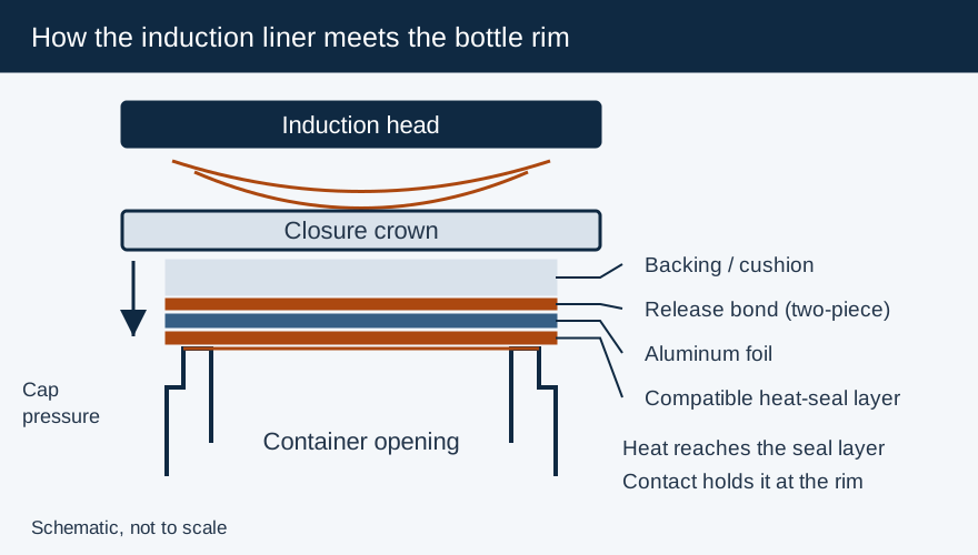
An induction cap sealer heats a foil innerseal so its heat-seal layer bonds to the container mouth. Cap pressure, material compatibility, head geometry and moving exposure must work together. Supply the equipment manufacturer with the lined closure, bottle, product and fill condition before comparing power ratings.
| Selection input | What to specify | What to demonstrate |
|---|---|---|
| Package | Cap profile, foil position, bottle material and product | Continuous bond and intended opening behavior |
| Cooling | Airflow/environment or water-cooling services | Operation within the chosen machine's installation limits |
| Head | Overhead, tunnel or application-specific tooling | Clearance and seal uniformity at production speed |
| Motion | Belt speed, spacing, stops and accumulation | Qualified exposure and safe stop/restart |
Compare real equipment configurations
Pillar lists a 2.25 kW supply for its iFoiler. Accutek lists a four-kilowatt automatic system with a water cooler/recirculator and heads for closures up to 12 cm. Enercon's Super Seal Jr is a manual timed unit with a standard head up to 83 mm and an optional head up to 120 mm. These examples describe different supplier configurations; match the selected machine and head to the actual production trial.
Air-cooled equipment requires its specified airflow and ambient conditions. A water-cooled installation adds coolant services, maintenance and related shutdown conditions. Review the utility schedule and intended duty with the supplier. Use the induction machine guide for selection inputs and the handheld guide for bench timing trials.
Set the head by foil position and clearance
A flat cap can keep the foil near an overhead head. A tall spout or other protrusion can require side-coupled tunnel geometry to bring energy closer to the foil. Pillar publishes a Universal coil range of 15–150 mm and two adjustable inFinity tunnel widths, 1–2¼ inches and 2¼–3½ inches. Check the whole package envelope against the selected head drawing.
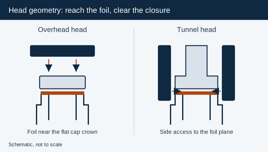
Enercon's illustrated conventional setup uses 1/8 inch clearance above the cap; deep-tunnel heads instead use a liner-height indicator. Align the installed head using its own instructions, keeping the cap path centered and the head parallel to the conveyor. The coil comparison covers tall and offset closures.
Qualify the window and the line stop
Hold material, cap application and running belt speed fixed while finding the successful energy range. Inspect cooled packages for bond, removal behavior and overheating. A container throughput figure alone cannot establish exposure because spacing and belt speed are separate inputs.
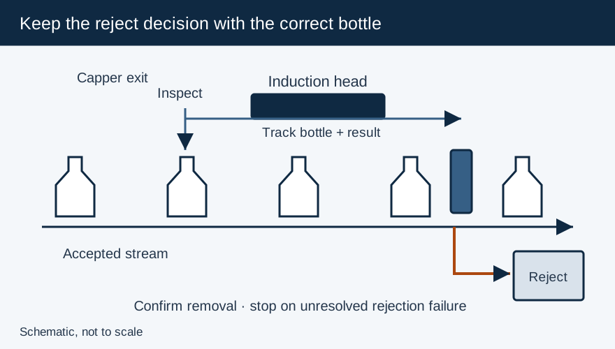
Enercon warns that bottles stalled beneath an energized head can overheat and create a fire risk, particularly with combustible contents. Have the qualified integrator assess stop protection, feed control, emergency stops and supplementary sensors together. Use the capping guide, sealer interface guide and full-line interface table for acceptance planning. When performance drifts, preserve samples and follow the troubleshooting sequence.
Primary references
- Enercon: Getting Started with Induction Cap Sealing
- Pillar Technologies — iFoiler™ Induction Cap Sealer Specifications
- Pillar Technologies — Induction Sealing Coils (Universal, inFinity Tunnel, C-Series Handheld)
- Accutek Packaging Equipment — Automatic 4 kW Water-Cooled Induction Sealer
- Super Seal™ Jr. - Handheld Induction Cap Sealing
- Safety Flammable Products - Enercon Industries Corporation