
Capping Machines Explained: Match the Cap, Container and Closing Process
Compare chuck, spindle, snap and ROPP closing mechanisms, then specify container support, torque checks and the capper-to-sealer interface.
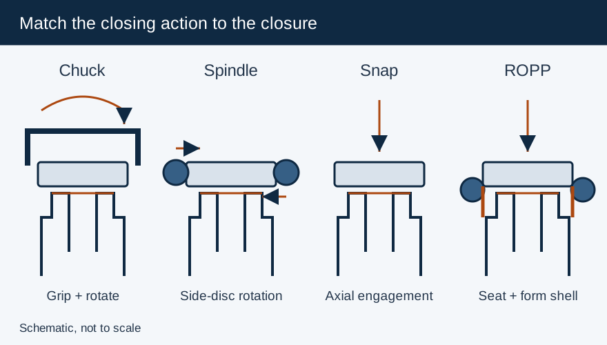
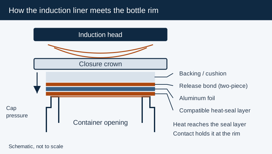
Match the capping mechanism to the closure before comparing machine speeds. A screw cap, press-on cap and roll-on aluminum shell require different closing actions; a mismatch can damage the finish or leave the liner unevenly seated. For induction sealing, the capper also supplies the pressure that keeps the foil against the bottle rim while the seal forms.
| Closing method | How it closes the package | Inputs to send the equipment supplier | Acceptance checks |
|---|---|---|---|
| Chuck | A head grips and rotates a threaded closure | Cap drawing, grip surface, torque requirement, bottle support | Seating, opening torque, cap damage, each head’s repeatability |
| Spindle | Rotating discs tighten the cap as the bottle advances | Cap diameter and profile, bottle stability, guide and belt settings | Cap alignment, bottle rotation, scuffing and torque variation |
| Snap/press-on | Axial force engages the closure’s retaining feature | Cap/neck engagement drawings and allowable container loading | Full engagement, deformation, opening performance |
| ROPP | A pressure block seats the liner while rollers form the shell around the glass finish | Matching cap and bottle finish, roller profiles, supplier head settings | Liner impression, rolled threads, pilfer-band formation and opening torque |
Choose the handling system with the closing head
E-PAK’s Chuck Cappers vs. Spindle Cappers describes a chuck gripping each closure and a spindle machine applying progressive side contact during conveyor travel. These mechanisms create different changeover work. A chuck may need a new insert for a changed cap profile; a spindle line needs its disc height, spacing and bottle gripping arrangement reset. Compare the actual proposed configurations using filled containers, including the tallest, least stable and most easily marked packages.
Ask the supplier to demonstrate feeding, orienting and applying the closure as a complete sequence. A cap that tightens correctly when hand-placed can still misfeed from a chute. Pumps, dispensing closures and child-resistant designs need particular attention to the surface the capper grips and the space available around protrusions. Include container support and guide settings in the changeover record, rather than recording only the torque dial.
Use a supplier torque range, then qualify the package
Enercon’s Getting Started with Induction Cap Sealing publishes general application-torque guidance. Selected entries are reproduced below as Enercon starting guidance for discussion with the cap and container supplier. The table is organized by nominal cap diameter; finish design, liner and resin still determine the approved production setting.
| Nominal cap diameter in Enercon’s guide | Application torque, lbf·in |
|---|---|
| 20 mm | 8–12 |
| 28 mm | 12–18 |
| 38 mm | 17–26 |
| 53 mm | 21–36 |
| 89 mm | 45–65 |
Measure application and removal torque as separate quantities. Specify when the removal measurement occurs and whether the sample has passed through induction sealing and cooling. Comparing samples tested at different stages can hide a change in the process. On a multi-head machine, keep head identity with the result so an individual head’s drift is visible.
Keep ROPP head load separate from screw-cap torque
An ROPP capper forms an initially unthreaded metal shell around its matching glass finish. The cork and screw-cap comparison explains why the bottle finish, pressure block and rolling tooling must be selected together. Chandler’s October 2020 sheet gives settings for a specific 0.23 mm, 8011-alloy, 30 × 60 mm screwcap on a BVS finish. Its load and torque guidance belongs to that cap system; apply the current cap supplier’s settings to another shell or finish.
Inspect the liner’s rim impression and the rolled geometry as well as opening torque. A torque result alone cannot show whether the entire sealing surface has been seated correctly. For a snap closure, use seating and retention checks appropriate to its engagement design instead of treating it as a screw cap.
Specify the capper-to-sealer handoff
Check that the closure stays square and seated through the transfer. Guide contact, uneven bottle support and accumulation can disturb the package before sealing. Enercon identifies low application torque, cocked caps and caps that bottom out on the bottle shoulder as causes of weak induction seals. Increasing sealer power will not correct missing mechanical contact.
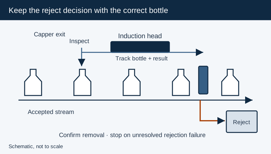
The handoff specification should state the accepted cap position, liner-presence check, running speed, stop signal and reject response. Challenge the line with known missing or misapplied closures under the equipment supplier’s safe test procedure. Verify that each challenged bottle reaches the reject location and that a stopped bottle cannot remain under an energized sealing head. Use the capper and induction-sealer integration guide to document those interfaces before production acceptance.
Frequently Asked Questions
How should application torque be selected?
Start with the cap and container suppliers’ recommendation, then qualify sealing and opening performance on the actual package. Record the method and timing of torque measurements.
Does a chuck capper automatically prevent cap damage?
Tooling fit, gripping force, container support and the cap surface all affect damage. Include cosmetic and functional inspection in the machine trial.
Primary Sources & Referenced Standards
- E-PAK Machinery — Chuck Cappers vs. Spindle Cappers Engineering Comparison
- ROPP Capping Technical Guide — Thread Rollers, Top Block Pressure & Pilfer Proofing
- Chandler / Vcap — ROPP 30x60 Capping Head Settings & Torque Specification Sheet (EN 16293 BVS Finish)
- Enercon: Getting Started with Induction Cap Sealing
More about Induction Sealing Machines
Electromagnetic induction cap sealers, flat vs. tunnel sealing coils, kW power-to-line-speed matching, capping head integration, and troubleshooting.
Related Articles
Capping and Induction Sealing: Line Interfaces and Rejection
Specify capper-to-sealer transfer, conveyor stop protection, inspection signals and confirmed rejection for an induction sealing line.
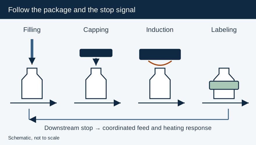
Integrating Filling, Capping and Labeling: Define Transfer, Timing and Reject Interfaces
Define conveyor, rate and reject interfaces between filling, capping, induction sealing and labeling, including safe stop and restart behavior.
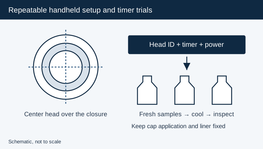
Handheld Induction Sealer Power, Time and Cap Diameter Guide
Choose the correct handheld head for small through 100 mm-plus caps, then qualify timer, power and centering on the actual bottle and liner.