
Capping and Induction Sealing: Line Interfaces and Rejection
Specify capper-to-sealer transfer, conveyor stop protection, inspection signals and confirmed rejection for an induction sealing line.
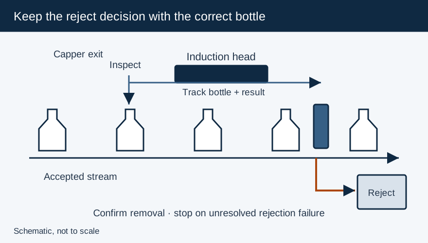
Integrate the capper and induction sealer around both package movement and fault response. The cap must reach the head seated correctly, and the line must remove heating exposure when a bottle stops beneath it. A sealer-ready signal, liner-presence sensor and reject actuator each answer a different question; connecting them does not by itself prove the finished seal.
| Interface | Required definition | Acceptance challenge |
|---|---|---|
| Capper discharge | Cap seating, liner presence, accepted torque method | Known misapplied and missing-liner samples |
| Transfer conveyor | Speed, centered path, head reference and accumulation behavior | Running-speed changes and downstream blockage |
| Sealer permissive | Conditions allowing product feed and coil operation | Power loss, sealer fault and stopped conveyor |
| Inspection to reject | Package tracking and defect identity | Adjacent good/bad packages and restart |
| Reject confirmation | Proof of removal and response to rejection failure | Blocked reject path or unavailable actuator under a safe test procedure |
Preserve the mechanical seal conditions through transfer
Enercon identifies sufficient cap application pressure as essential to induction sealing. Verify caps immediately after the capper and at the sealer entrance, using a consistent inspection and torque method. Inspect guide contact, container support and cap orientation where the conveyor changes direction or transfers between sections.
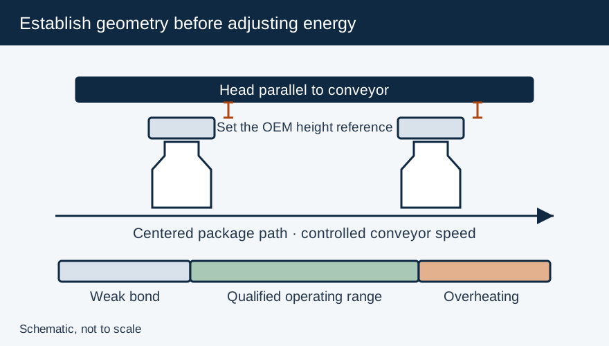
Record belt speed, not only bottles per minute. The induction exposure follows the motion beneath the head. If the line changes speed, confirm how the sealer responds and whether the package remains within its qualified operating range. The machine selection guide explains pressure, heat and time; this interface record should carry the approved settings and stop actions.
Design the stop sequence before locating sensors
Enercon’s Safety Flammable Products notice warns that containers can collect under a sealer during a jam or stall, overheating contents and creating a fire risk. It recommends professional assessment of the entire packaging line and emphasizes that detectors supplement emergency stops and other interlocks.
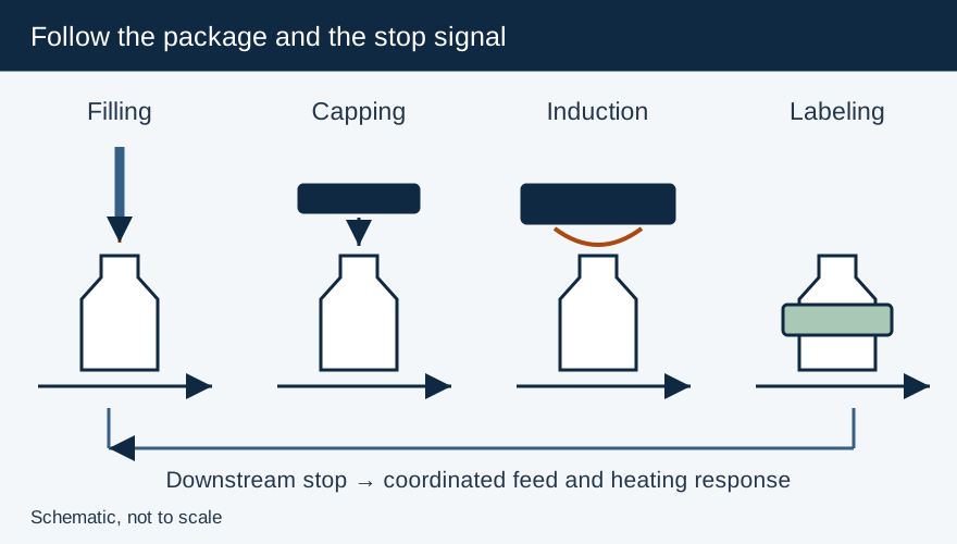
Have the integrator define the response to conveyor stop, downstream backlog, sealer fault and loss of power. Heating exposure must end when motion is lost under the head. Control upstream feeding so additional packages do not enter a disabled sealing process. Establish how affected bottles are identified, held and evaluated after a stop, including bottles whose exposure was interrupted.
Pillar’s Verification Variables describes optional stalled-bottle, loose-cap and missing-foil functions, as well as an infeed stop associated with power loss or unexpected stopping. Confirm which functions are installed and their actual I/O behavior; an option listed in a product brochure is not proof that it exists on the machine.
Connect inspection to the correct physical bottle
Document the detection point, distance to the reject point, transport behavior and tracking method. Where speed varies, verify that the controller preserves bottle identity rather than assuming a fixed transit time. If the package slips, accumulates or transfers between conveyors, the tracking design must account for that movement.
Challenge the system using distinguishable known-defect samples among good containers at the intended spacing and operating speeds. Confirm the defect is detected, the correct bottle is diverted and the rejection is acknowledged. Also test the line’s defined response when rejection cannot be completed. Keep the challenge procedure within the OEM’s safe operating instructions.
Separate presence checks from seal verification
Missing-foil detection establishes whether the relevant sensor sees foil. High-cap detection screens seating problems. Neither directly measures the bond around the entire rim. Add an appropriate seal-integrity or seal-quality method for the package risk and use its results when qualifying the operating window.
For thermal inspection, verify the system with representative good and defective seals, including the specified inspection timing and package materials. A heat pattern can identify process variation, but its relationship to a leak must be demonstrated for that package. Preserve each sensor’s intended defect class in the specification so operators know what a passing result means.
The final acceptance record should include the package recipe, interlock cause-and-effect table, sensor challenges, reject confirmation, stop/restart disposition and responsible approval. Recheck affected functions after a cap, liner, bottle, conveyor or control-system change. For the wider filler and labeler interfaces, use the full-line integration guide.
Primary Sources & Referenced Standards
- Enercon: Getting Started with Induction Cap Sealing
- Pillar Technologies — Sealing Unit Verification (SUV) & Line Interlock Variables
- Cap Inspection - Induction Cap Sealing
- Enercon Cap Sealer Network & I/O Control Comparison - Induction Cap Sealing
- Safety Flammable Products - Enercon Industries Corporation
More about Induction Sealing Machines
Electromagnetic induction cap sealers, flat vs. tunnel sealing coils, kW power-to-line-speed matching, capping head integration, and troubleshooting.
Related Articles
Capping Machines Explained: Match the Cap, Container and Closing Process
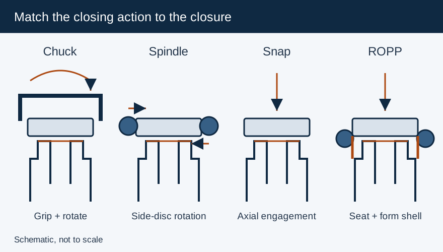
Compare chuck, spindle, snap and ROPP closing mechanisms, then specify container support, torque checks and the capper-to-sealer interface.
Integrating Filling, Capping and Labeling: Define Transfer, Timing and Reject Interfaces
Define conveyor, rate and reject interfaces between filling, capping, induction sealing and labeling, including safe stop and restart behavior.
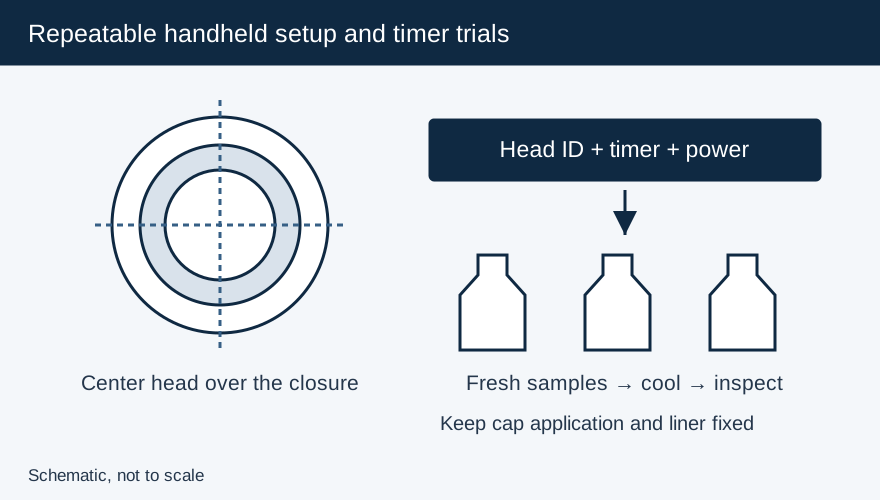
Handheld Induction Sealer Power, Time and Cap Diameter Guide
Choose the correct handheld head for small through 100 mm-plus caps, then qualify timer, power and centering on the actual bottle and liner.