
Induction Cap Sealer Coil Selection: Flat Coil vs Tunnel Coil for Dispensing and Tall Caps
Compare overhead and side-coupled induction heads using foil height, cap profile, bottle clearance and supplier-specific coil ranges.
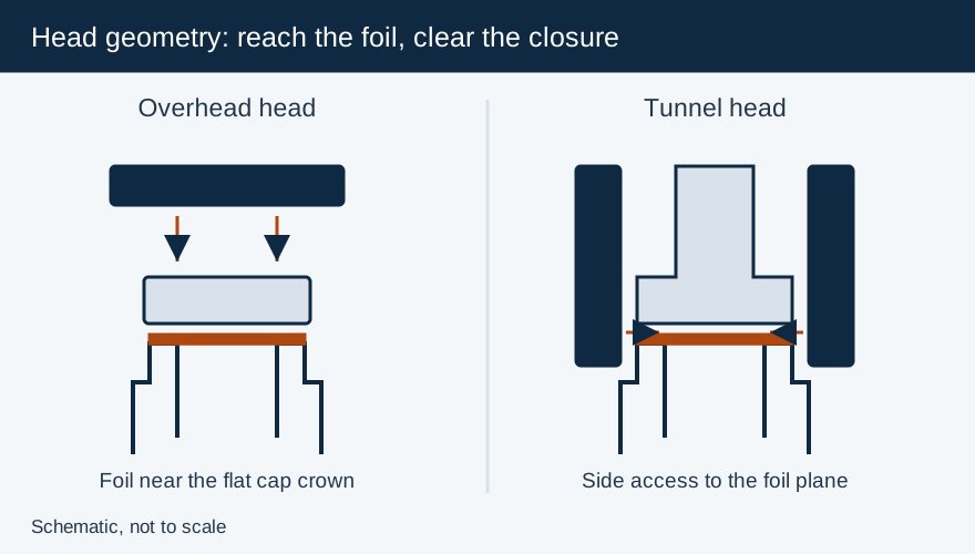
Choose a sealing head around the foil’s position and the space available around the cap. A tall dispensing spout can force an overhead coil away from the foil; a tunnel head can bring the field closer from the sides. Selecting by cap diameter alone can leave part of the seal underheated or create a mechanical collision with the bottle shoulder.
| Supplier head example | Published application or range | Alignment decision |
|---|---|---|
| Pillar Universal coil | Flat and child-resistant caps, 15–150 mm | Adjust angle to the cap path using the entrance and discharge indicators |
| Pillar inFinity tunnel | Adjustable widths of 1–2¼ inches or 2¼–3½ inches | Align side indicator lines with the foil level |
| Enercon flat head | Broad field suited to larger flat closures | Verify the selected head’s cap coverage and conveyor path |
| Enercon tunnel/deep tunnel | Concentrated field around closure sides; dispensing/tall-cap applications | Match cap and shoulder clearance and the specified foil-height reference |
The Pillar widths describe its adjustable tunnel configurations. Check the complete head drawing before treating a channel width as an approved cap size.
Trace the field path from coil to foil
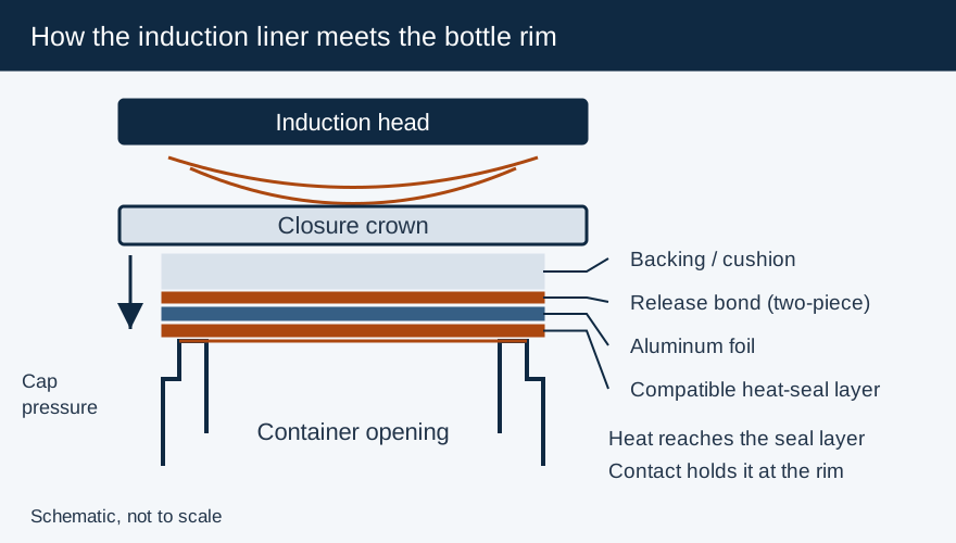
Enercon explains that head geometry and foil size influence the energy transferred to the liner. Pillar describes its Universal coil applying the field from above and its inFinity tunnel applying the field from the sides, leaving space above for tall caps. This is why a different head can solve a geometry problem that a power adjustment does not.
Measure cap height, foil position, outside profile and the container’s shoulder envelope. For a flip-top, include the hinge. For a nozzle, include its maximum height and manufacturing variation. For an offset jug opening, describe where the closure travels relative to the conveyor and whether the body constrains lateral positioning.
Flat or universal coils: verify the actual cap path
A flat coil is a practical candidate for flat closures with the foil near the crown. Pillar’s Universal coil also supports child-resistant caps, although the added separation can affect line speed; Pillar suggests a tunnel or higher-powered system for some such applications. A child-resistant or dispensing label alone does not determine the head: use the actual geometry and the required speed.
For the Pillar Universal coil, the published setup aligns the entrance indicator just beyond one cap edge and the discharge indicator beyond the opposite edge. This angle setting is part of the package recipe. A head changeover can require more than raising or lowering the assembly.
Tunnel heads: check side clearance and foil height together
A tunnel head can place energy nearer the foil below a tall closure. Pillar instructs users to align its indicator lines with the foil layer. Enercon’s deep-tunnel setup likewise uses a liner-height reference. Follow that reference rather than transferring a conventional overhead cap-gap instruction.
Use the full moving envelope to assess clearance. The cap might fit the channel while a sloping shoulder or handle collides with its lower edge. Check normal running, bottle lean, guide adjustment and changeover extremes under the supplier’s safe setup procedure. Custom or split tooling is a supplier engineering decision for unusual geometry; prove the proposed solution at production speed.
Qualify the head and power supply as a combination
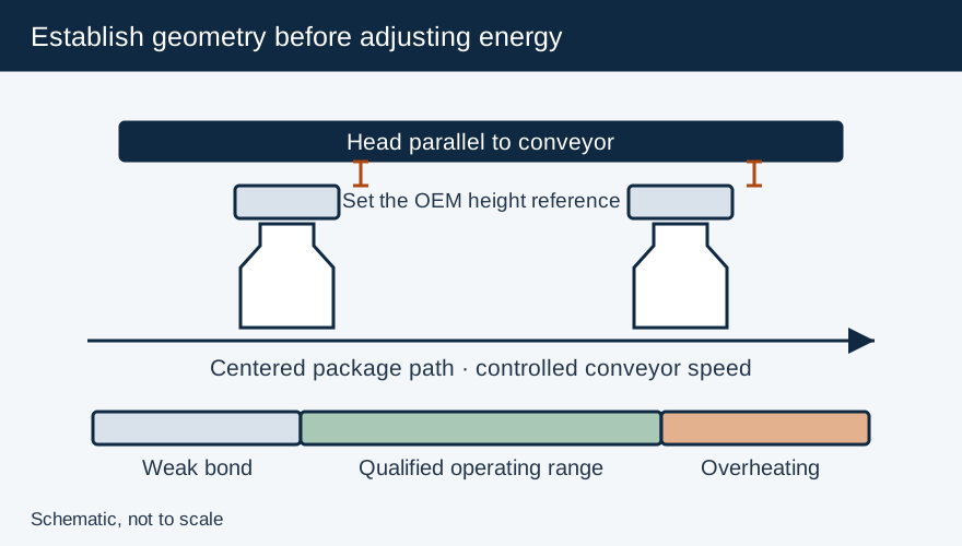
Prepare the intended lined cap and filled bottle, establish the approved application condition and center the package path. At the intended belt speed, find the range that produces the required bond and opening behavior without damaging the liner or container. Inspect the full rim, including the sides most affected by a displaced or tilted package.
Compare candidate heads with the same material lots and acceptance method. Record head identity, angle or width adjustment, height reference, guide positions, belt speed and power. Check startup, planned stops and restart with the line integrator; stop protection remains necessary regardless of coil shape.
For recurring partial seals, use the five-factor diagnosis before replacing the head. Low cap pressure, rim defects and incompatible liner material can produce failures that resemble poor coupling. The correct selection is the head/package combination that meets the validated operating window, not the one that reaches the highest displayed power.
Frequently Asked Questions
Do all flip-top caps require tunnel heads?
Decide from the cap geometry, foil position and required line speed. A tunnel is useful when the closure forces an overhead head too far from the foil; supplier trials establish the suitable configuration.
What should be measured on an offset jug cap?
Supply the foil position, cap profile, shoulder/handle envelope and the closure’s path relative to the conveyor. Verify clearance and seal uniformity with the proposed head.
Primary Sources & Referenced Standards
More about Induction Sealing Machines
Electromagnetic induction cap sealers, flat vs. tunnel sealing coils, kW power-to-line-speed matching, capping head integration, and troubleshooting.
Related Articles
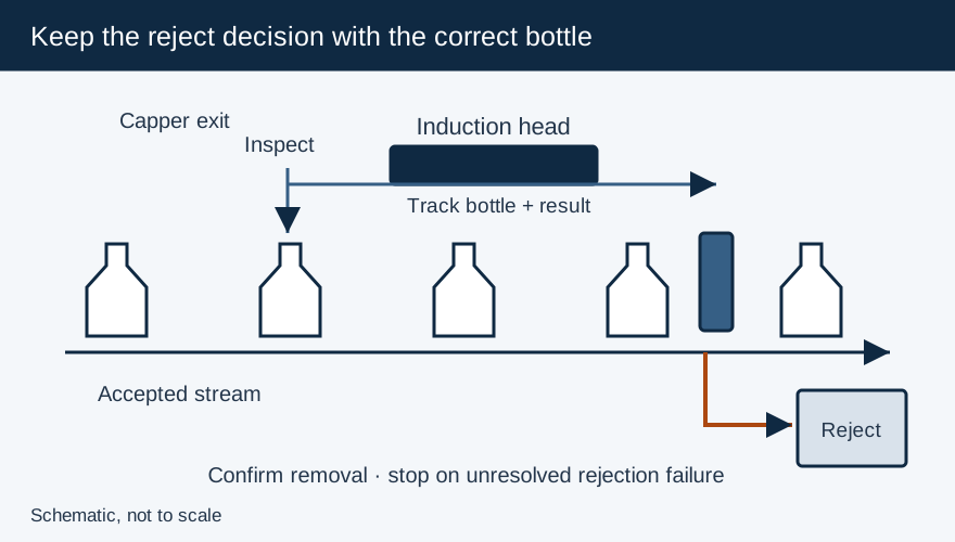
Capping and Induction Sealing: Line Interfaces and Rejection
Specify capper-to-sealer transfer, conveyor stop protection, inspection signals and confirmed rejection for an induction sealing line.
Capping Machines Explained: Match the Cap, Container and Closing Process
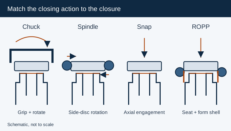
Compare chuck, spindle, snap and ROPP closing mechanisms, then specify container support, torque checks and the capper-to-sealer interface.
Integrating Filling, Capping and Labeling: Define Transfer, Timing and Reject Interfaces
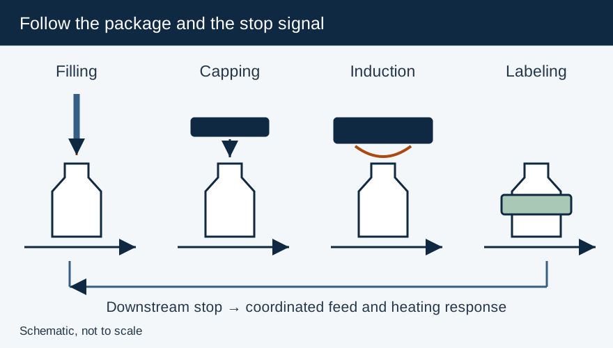
Define conveyor, rate and reject interfaces between filling, capping, induction sealing and labeling, including safe stop and restart behavior.