
Induction Seal Application Torque Window: Liner Compression vs Coil Power
Set up your induction seal application torque trial with starting guidelines, removal-torque checks, contact inspection and a blank package record.
Proper application torque provides downward pressure for contact between the foil and container lip.
Induction sealing equipment cannot compensate for poor cap application torque.
The foil disc must heat sufficiently to melt the polymer layer on the liner.
On cooling, the polymer adheres to the liner and container lip.
Start with the package, then work through the torque and heating checks below. For the wider selection task, use our cap liner selection guide.
Choose the application-torque starting point
Optimum torque depends on the container, closure design and liner material.
Packagers should follow the cap supplier’s torque recommendations and validate the results for each induction sealing application.
Enercon UK starting guidelines
-
The starting guideline for a 38 mm closure is approximately 18–20 in-lb.
-
The starting guideline for a 63 mm closure is approximately 30–32 in-lb.
Use these starting guidelines alongside the package-specific trial record below. Keep the chosen closure and liner together in that record; see the induction liner guide for the selection step.
Verify application torque across every capping head.
Regularly calibrate capper settings as part of preventative maintenance.
Inspect liner contact before adjusting coil power
Insufficient or uneven liner pressure on the land area results in poor seals.
A liner that is too thick or rigid can prevent consistent closure pressure on the land area.
Oversize liner overhang can interfere with uniform pressure.
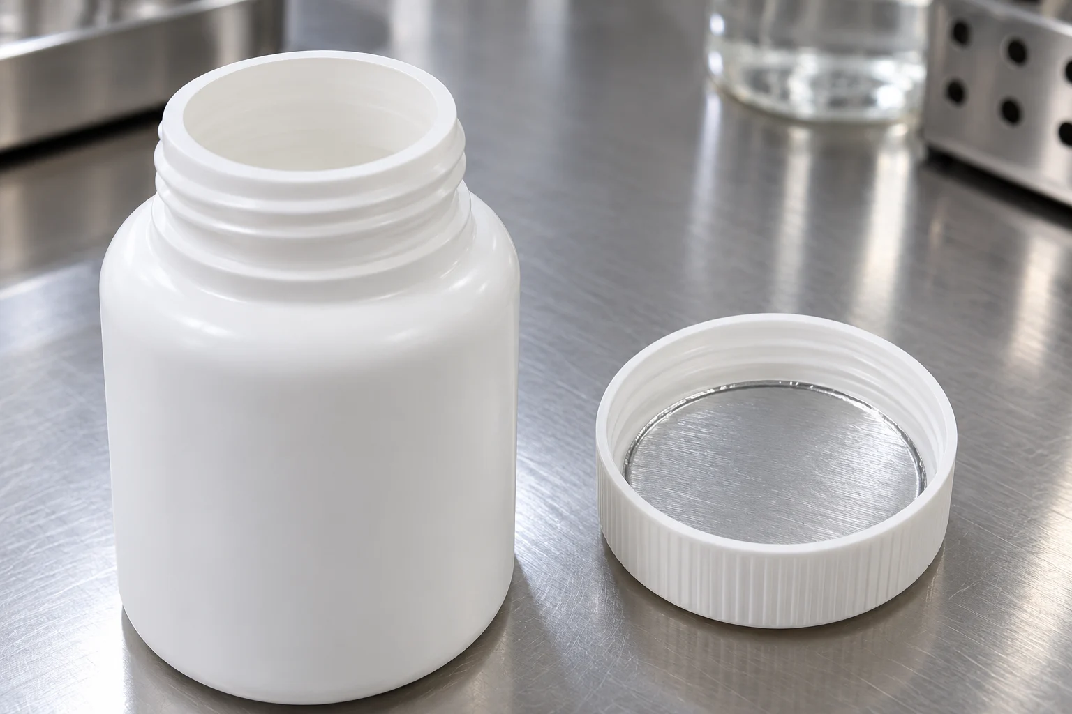
For the mechanical check, work through the closure fit:
-
Confirm that the cap is not stripping or jumping threads and relieving contact pressure.
-
Check that the closure skirt does not bottom out on the container neck.
-
Lower application torque if it distorts the cap or bottle.
Low closure on-torque is a probable cause of partial seals or a high percentage of leakers.
Excessive application torque with stripped threads is a probable cause of very little or no removal torque.
For an already damaged seal, continue to the adhesion failure and overheating guide.
Separate immediate removal torque from post-seal removal torque
In Enercon’s immediate-removal protocol, removal torque is measured one minute after capping, before sealing.
Under that immediate-removal protocol, removal torque should be about 50% of application torque.
Immediate-removal example
For a 38mm closure applied at 18 in-lbs, immediate removal torque is approximately 9 in-lbs.
Keep the example with the pre-sealing check above. Record the post-sealing measurement separately.
Post-sealing removal torque is likely lower than immediate removal torque.
The amount of removal-torque change varies with the heat induction seal material.
The heat seal layer compresses as it flows and adheres to the container land area.
With a two-piece liner that has a wax release layer, the wax is absorbed into the pulp board secondary liner, reducing overall liner height.

Measure removal torque after induction sealing.
A lightly applied closure is a probable cause of very little or no removal torque.
Read the application setting, immediate-removal result, post-sealing result and thread observations together in the record.
Establish the heating window with torque controlled
Hold conveyor speed and application torque fixed and record both while setting the induction process.
Dwell Time = Sealing Head Length/Speed of Line.
Low power for line speed is a probable cause of weak or absent seals.
Too little heat produces a weak seal; too much heat can burn or deform liners.
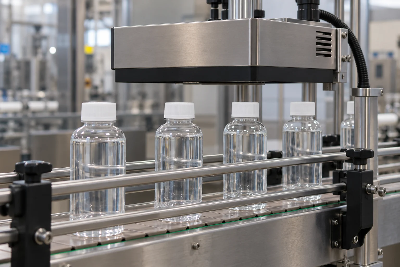
In Pillar’s operating-window procedure, the upper power boundary retains a complete seal without burning or melting inside the cap or melting the bottle lip.
Prohibit aggressive handling or impacts while the bond cools after induction heating.
Retorquing too soon after induction sealing is a probable cause of liner pinwheeling.
Package and torque trial record
Copy this blank record for your package trial. Give the pre-seal and post-seal samples their own identifiers.
| Record group | Your entries |
|---|---|
| Package | Container; closure; cap diameter; liner grade; foam or backing construction |
| Torque specification | Package-specific lower and upper limits; units; specification reference |
| Capping | Capper head; application setting; measured application torque; sample identifier |
| Immediate removal | Sample identifier; elapsed time after capping; pre-seal removal torque |
| Induction trial | Conveyor speed; sealing head; coil position; power setting |
| Post-seal removal | Sample identifier; cooling duration; measurement time; removal torque |
| Observations | Rim bond; liner appearance; cap or bottle distortion; thread condition |
| Decision | Selected torque and heating settings; acceptance basis; follow-up action |
For your next package review, assemble the application torque, removal torque, bottle-mouth diameter and liner foam or backing structure. Continue with cap liner selection and keep the completed record with the package specification.
Sources
-
Enercon — Improve Your Induction Cap Sealing IQ
-
Enercon UK — Importance of Cap Application Torque
-
Selig Group — Guide to Successful Sealing
-
Selig Group — FAQs & Troubleshooting
-
Enercon — Understanding application & removal torque
-
TricorBraun — Foil Induction Sealing Guidelines
-
Pillar Technologies — Improve your Induction Sealing Results
-
SKS Bottle — Understanding Induction Liners
More about Cap & Liner Selection
One-piece and two-piece wax-backed or polymer-bonded foil innerseals, container resin compatibility (PE, PP, PET, PVC, glass), and ROPP vs. cork closures.
Related Articles
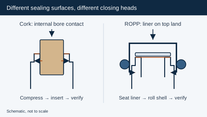
Cork vs Screw Cap: What Changes in the Bottling and Closing Process?
Compare still-wine cork insertion and ROPP screw capping by bottle finish, closing action, headspace control, liner and release tests.
Induction Foil Seal Adhesion Failure and Overheating Troubleshooting Guide
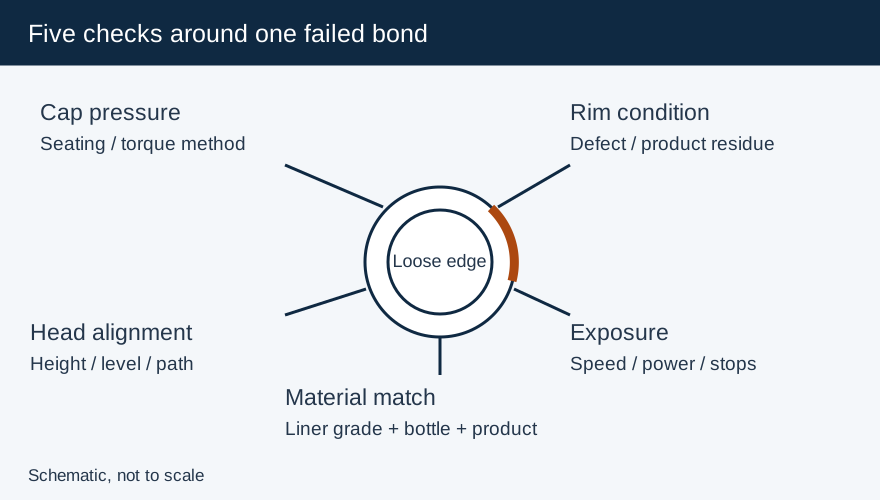
Use five checks—cap pressure, rim condition, coil alignment, conveyor exposure and material match—to isolate foil adhesion failure and overheating.
Induction Seal Liners: One-Piece vs Two-Piece Wax-Backed Construction and Container Matching
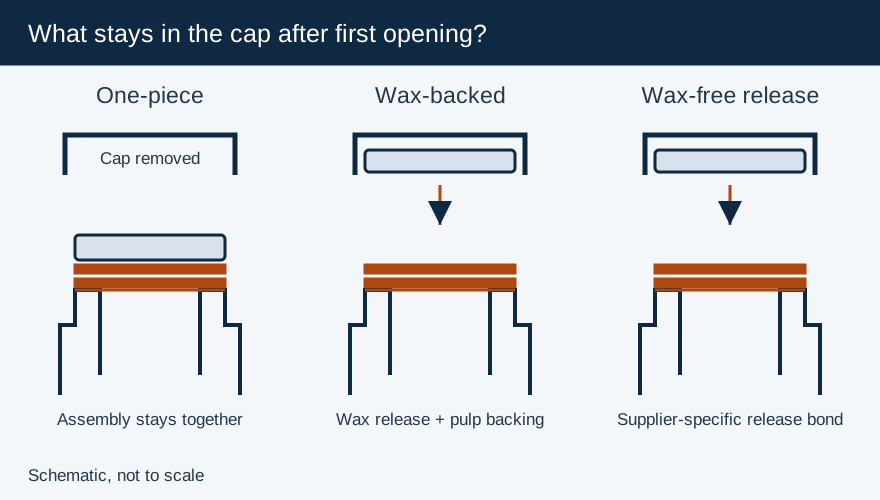
Compare one-piece, wax-backed two-piece and wax-free release liners, including layer function, backing retention and container compatibility.