
Induction Sealing Machines: Liners, Containers and Trial Checks
Select induction power, cooling and sealing heads using actual package geometry, then qualify pressure, heat and conveyor time together.
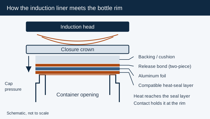
Select an induction sealing machine around the filled container, lined cap and required conveyor speed. The power supply rating is one input; cap geometry and the sealing head determine how effectively energy reaches the foil. Poor liner contact can leave an unsealed edge even when added power overheats the rest of the liner.
| Published equipment example | Supplier’s stated feature | Selection implication |
|---|---|---|
| Pillar iFoiler | 2.25 kW power supply; interchangeable sealing coils | Select the coil and demonstrate the required package/speed combination |
| Accutek Automatic Induction Sealer | Four-kilowatt system with water cooler/recirculator; heads for closures up to 12 cm | Include cooling services and a head sized for conveyor exposure in the installation review |
| Enercon Super Seal Jr | Manual timed operation; standard head up to 83 mm, optional head up to 120 mm | Identify the supplied head and account for manual handling in batch capacity |
These are representative supplier configurations. Obtain the current equipment drawing, utility schedule and application trial for the exact machine being purchased.
Pressure, heat and time must work together
Enercon’s Getting Started with Induction Cap Sealing describes a power supply delivering high-frequency current to a sealing head. The resulting magnetic field heats the conductive foil; that heat activates the liner’s heat-seal layer against the container lip. The cap holds the laminate in contact while the seal forms.
The three process controls are coupled. Application torque establishes contact; power and head geometry influence heat delivery; conveyor motion determines exposure. A higher power setting can compensate for some speed changes within a qualified operating range, but it cannot repair incompatible liner chemistry or a cap that is cross-threaded. Resolve those conditions before adjusting energy.
For a conveyor head, exposure time varies with the effective heated path and belt speed. Record belt speed in distance per time as well as container throughput. Bottles per minute alone does not describe how long each cap remains under the coil, because bottle spacing also changes throughput.
Choose cooling and head geometry for the installation
Air-cooled equipment needs the airflow and ambient conditions specified by its manufacturer. Water-cooled equipment adds coolant circulation, maintenance and shutdown conditions to the installation. Compare required services, environment, duty cycle and available support alongside rated power.
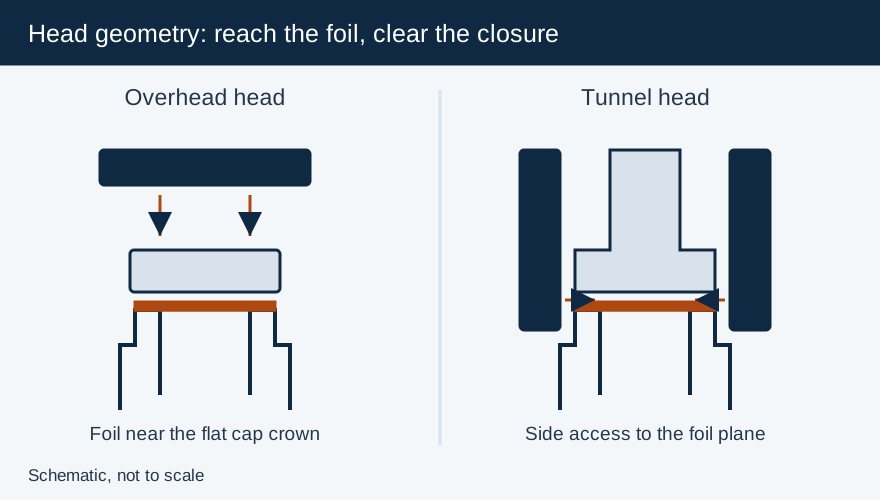
For a flat cap whose foil lies near the top, an overhead coil can be effective. A tall dispensing closure may put the foil much farther from the overhead head; a tunnel design can bring the field closer from the sides. The flat-versus-tunnel guide compares supplier geometry and alignment instructions. Metal closures and unusual package arrangements need the sealer supplier’s application assessment.
Establish the mechanical setup before finding the sealing window
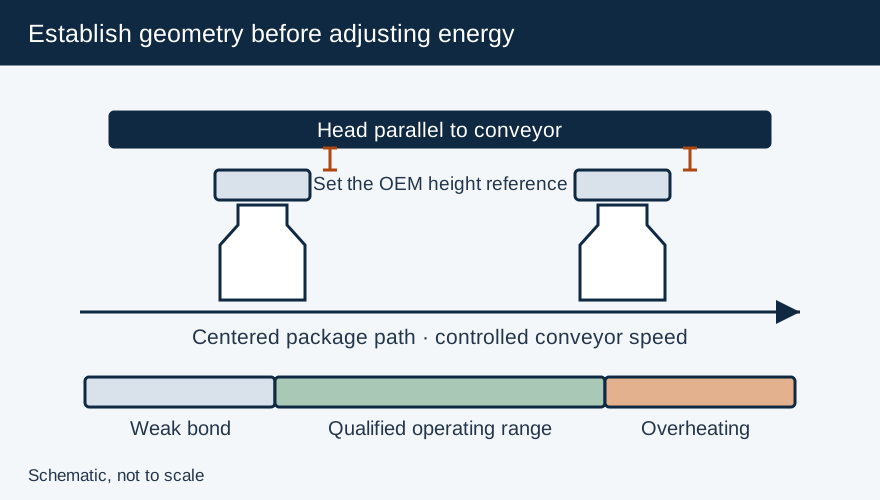
Center the package path and make the head parallel to the conveyor. Enercon’s guide gives 1/8 inch above the cap for its illustrated setup, with deep-tunnel heads instead aligned to the liner-height indicator. Use the installed head’s instructions for clearance and height; a deep tunnel’s alignment reference is different from an overhead cap gap.
Keep cap torque, liner specification, fill condition and production speed fixed while establishing the lower and upper usable power boundaries. Inspect cooled samples for continuous bonding and the specified opening behavior. Watch for wrinkles, odor, discolored backing or foam deformation as overheating indicators. Select an approved setting inside the successful window and confirm it on representative production lots.
Prove stop protection and package performance
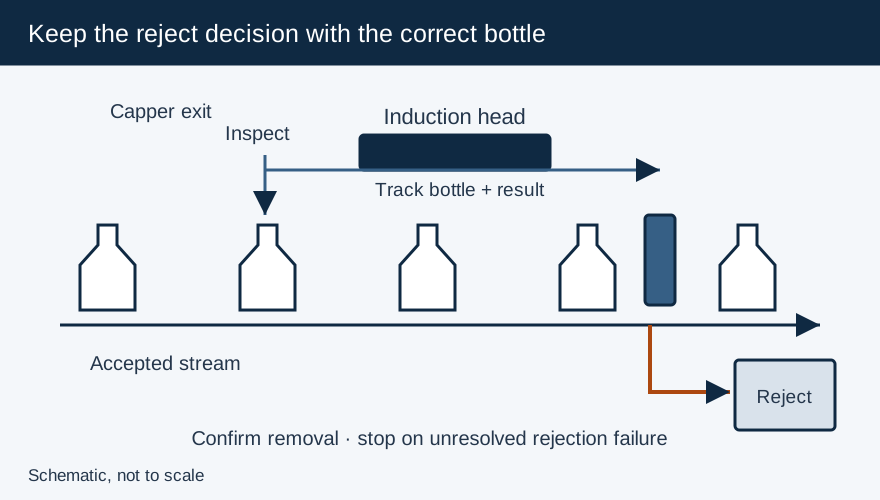
Enercon’s Safety Flammable Products notice warns that a jam or stall can hold containers beneath the head, overheat contents and create a fire risk, especially with combustible material. Have the line integrator assess shutdowns, emergency stops, stalled-bottle detection and upstream accumulation together. Detection sensors supplement the required interlocks; they do not replace them.
Qualify seal performance using a method matched to the package’s intended protection. Liner presence and cap-height sensors screen particular defects; a passing sensor signal alone does not establish a sound bond. Pair the trial with closure integrity testing, retain the approved recipe and recheck the window after changes to material, speed, head or filling conditions.
Frequently Asked Questions
Is there one standard gap for all induction heads?
Use the installed head’s instructions. Enercon illustrates a 1/8 inch cap clearance for its conventional setup, while deep-tunnel heads use a liner-height indicator.
Can power rating determine bottles per minute?
Package geometry, head design, spacing, conveyor speed and material response all affect capacity. Prove the requested throughput with the actual package.
Primary Sources & Referenced Standards
More about Induction Sealing Machines
Electromagnetic induction cap sealers, flat vs. tunnel sealing coils, kW power-to-line-speed matching, capping head integration, and troubleshooting.
Related Articles
Capping and Induction Sealing: Line Interfaces and Rejection
Specify capper-to-sealer transfer, conveyor stop protection, inspection signals and confirmed rejection for an induction sealing line.
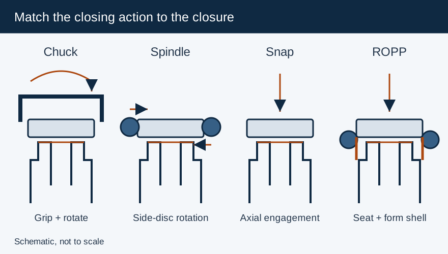
Capping Machines Explained: Match the Cap, Container and Closing Process
Compare chuck, spindle, snap and ROPP closing mechanisms, then specify container support, torque checks and the capper-to-sealer interface.
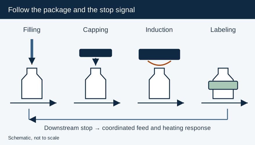
Integrating Filling, Capping and Labeling: Define Transfer, Timing and Reject Interfaces
Define conveyor, rate and reject interfaces between filling, capping, induction sealing and labeling, including safe stop and restart behavior.