
Vacuum Decay Leak Testing: Principle, Cycle & Fit
How ASTM F2338-24 vacuum decay leak testing detects non-visible micro-leaks in rigid bottles, trays, and flexible packages without destroying samples.
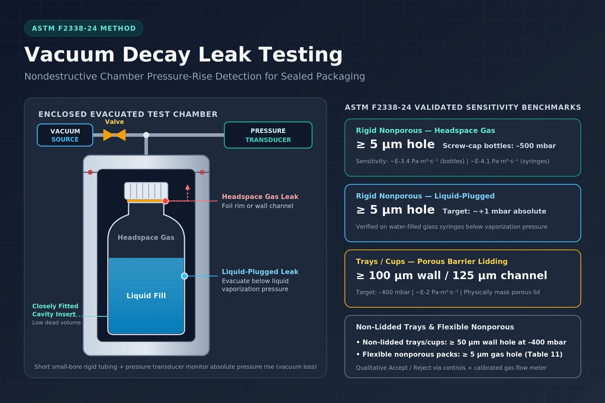
Vacuum decay leak testing detects non-visible micro-leaks in sealed packages without dyes, tracer gases, or sample destruction by enclosing the container in an evacuated test chamber and measuring pressure rise with pressure transducers. Under ASTM F2338-24, escaping headspace gas or volatilized liquid raises chamber pressure above an intact-control baseline, down to 5 μm holes in nonporous packages.
Within a plant-wide seal integrity testing program, vacuum decay provides objective leak-rate verification after capping and induction sealing without puncturing bottles or submerging closures in fluid. Packaging engineers comparing nondestructive micro-leak verification against gross immersion methods can map each method to its defect scope in the container closure integrity testing guide.
What Is the Principle Behind Vacuum Decay Leak Testing?
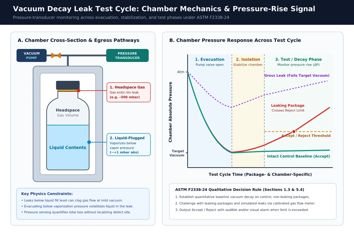
Vacuum decay leak testing places a sealed package inside an enclosed evacuated chamber and tracks absolute pressure rise (vacuum loss) over time using one or more pressure transducers. Because leaks allow unwanted gases such as oxygen, microbiological contaminants, or particulates to enter through component walls or seal junctures, pressure egress directly reveals closure breaches.
Headspace Gas Leakage vs. Liquid-Plugged Defects
In a sealed bottle or tray with dry contents or an open gas headspace above the defect, drawing chamber vacuum creates a pressure differential that pulls internal headspace gas out into the evacuated cavity. When a defect sits below the fill level, however, product can obstruct the pathway: peer-reviewed vial headspace research published in Sensors (2023) notes that leaks located below the product fill level may clog the flow of leaking gas during vacuum decay testing.
To overcome liquid occlusion, ASTM F2338-24 specifies evacuating the test chamber to a pressure below the liquid’s vaporization pressure whenever a leak may be partially or completely plugged with liquid contents. Once chamber pressure drops below that vaporization threshold, liquid located in or near the micro-channel flashes to vapor, generating a measurable pressure rise in the transducer signal. Engineers correlating dry-gas screening to liquid retention also account for fluid physics: as reported in a 2022 Frontiers in Bioengineering and Biotechnology leakage review, an air-based leak test produces 51 times the amount of leaked medium compared to water under viscosity-governed flow assumptions.
Dead Volume Dilution, Porous Masking, and Non-Localization
Key physical boundaries control whether a vacuum decay test produces reliable Accept/Reject calls:
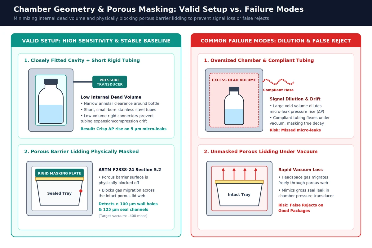
- Internal dead volume and tubing compliance: Because the internal volume of a gas-based leak test setup directly governs pressure-sensor sensitivity, excessive void space around the bottle dilutes the pressure rise from a micro-leak. The 2022 leakage testing review recommends minimizing internal volume with short, small-cross-section tubing, low-volume connectors, and stainless steel tubes instead of compliant tubing that expands or compresses under pressure changes.
- Physical masking of porous barrier surfaces: ASTM F2338-24 requires physically masking or blocking off any porous barrier surface on the package during testing. Without a blocking surface, gas migration through the intact porous web causes rapid chamber vacuum loss and triggers false rejects.
- Whole-package signal without defect localization: Pressure-based leak measurements evaluate the entire enclosed package at once. While transducer decay quantifies total leakage reliably, pressure measurement alone makes it difficult to pinpoint the exact physical location of a leak without secondary inspection.
What Is the ASTM Standard for Vacuum Leak Testing?
The primary ASTM standard for nondestructive vacuum leak testing is ASTM F2338-24, Standard Test Method for Nondestructive Detection of Leaks in Packages by Vacuum Decay Method, maintained by Subcommittee F02.40 in Book of Standards Volume 15.10 (14 pages, DOI 10.1520/F2338-24, ICS Code 55.180.40, last updated Nov 14, 2024).
In ASTM F2338-24, SI units are regarded as standard and no other units of measurement are included. On the regulatory side, the U.S. FDA CDRH Recognized Consensus Standards database grants Complete standard recognition to ASTM F2338-09 (Reapproved 2020) under Sterility Recognition Number 14-282 (FR Recognition List Number 036, entered 07/09/2014). FDA cites the method as relevant for all medical devices where sterilization and packaging are part of product development and manufacture, alongside ISO 11607-1, ISO 11607-2, and ISO/TS 16775 (First edition 2014-05-15).
Validated Package Categories and Target Vacuum Levels
| ASTM F2338-24 Package Category | Leak Medium Evaluated | Minimum Validated Defect Size | Target Vacuum Level | Volumetric Airflow Sensitivity |
|---|---|---|---|---|
| Rigid and semi-rigid non-lidded trays or cups | Air leakage through wall | Hole or crack at least 50 μm diameter | –4·E4 Pa (–400 mbar) | Established via precision and bias studies |
| Trays or cups with porous barrier lidding (masked) | Headspace gas leakage | Wall hole/crack at least 100 μm; seal wire channel 125 μm; severe adhesive defects | –4·E4 Pa (–400 mbar) | Approximately E-2 Pa·m³·s⁻¹ |
| Rigid nonporous packages — screw-cap plastic bottles | Headspace gas leakage | Hole defect at least 5 μm diameter | –5·E4 Pa (–500 mbar) | Approximately E-3.4 Pa·m³·s⁻¹ |
| Rigid nonporous packages — air-filled glass syringes | Headspace gas leakage | Hole defect at least 5 μm diameter | –7.5·E4 Pa (+250 mbar absolute) or ~+1 mbar absolute | Approximately E-4.1 Pa·m³·s⁻¹ |
| Rigid nonporous packages — water-filled glass syringes | Liquid leakage (volatilization) | Hole defect at least 5 μm diameter | About +1 mbar absolute | Verified below liquid vaporization pressure |
| Flexible nonporous packages | Gas or liquid leakage | Hole defect at least 5 µm diameter (gas, Table 11) | Package-specific validated vacuum | Established via Table 11 pack population |
Scope Boundary Against ASTM D5094/D5094M-24
Teams evaluating rigid liquid bottles should distinguish ASTM F2338-24 micro-leak testing from gross-leak distribution methods. ASTM D5094/D5094M-24 (Standard Test Methods for Gross Leakage of Liquids from Containers with Threaded or Lug-Style Closures) checks gross liquid leakage in rigid and semi-rigid containers up to 4 L to assess distribution survival, using Test Method A (shipping vibration and high-temperature storage) or Test Method B (an individual-container vibration and vacuum chamber test that is usually less severe than Test Method A and offers a shorter duration), and may not suit hazardous-material transport containers. Similarly, destructive immersion methods belong in the bubble leak test guide, while container resin and glass rim bonding differences belong in the PET vs glass bottle induction sealing guide.
How Do You Run a Vacuum Decay Test?
Running a valid vacuum decay test starts with establishing quantitative baseline decay on control non-leaking packages, challenging the fixture with leaking packages and a calibrated gas flow meter to lock qualitative Accept/Reject limits, and masking any porous barrier surfaces before evacuating production samples to the validated target vacuum.
- Match the chamber and mask porous surfaces: Seat the sealed package inside a closely fitted test chamber sized to minimize annular dead space. For trays or cups sealed with porous barrier lidding, engage a rigid physical masking plate across the porous surface so gas migration cannot bleed chamber vacuum.
- Establish the control baseline: Evacuate a population of verified control non-leaking packages to the target vacuum (for example, –500 mbar for plastic screw-cap bottles tested for headspace gas, or about +1 mbar absolute for water-filled rigid containers with liquid-plugged leak risk) and log their quantitative baseline vacuum decay measurements.
- Challenge with leaking controls and a calibrated gas flow meter: Run known leaking packages and introduce simulated leaks using a calibrated gas flow meter to verify detection of the target defect size and set the qualitative Accept/Reject cutoff above normal intact-package background drift.
- Execute the production cycle: Operate the validated recipe in manual, semi-automatic, or automatic mode. The system evacuates the enclosed chamber, isolates the vacuum source, and monitors pressure rise across the pressure transducer without introducing dyes or extraneous gases.
- Act on audible or visual alarms and localize defects offline: Under ASTM F2338-24, leak test results exceeding permissible limits trigger audible or visual signal responses, or both. Because whole-chamber pressure decay flags the failing unit without marking the exact pinhole site, route rejected induction-sealed bottles to offline rim inspection and the induction sealing troubleshooting guide.
Vacuum Decay Chamber Matching and Baseline Checklist
Use this pre-qualification checklist when matching a test chamber to a new bottle, tray, or flexible package format and locking in the qualitative Accept/Reject baseline.
| Verification Item | Requirement to Confirm | Engineering Target / Record |
|---|---|---|
| Package class and leak medium | Classify package under ASTM F2338-24 and identify gas vs liquid-plugged defect risk | Non-lidded tray, porous-lidded tray, rigid nonporous, or flexible nonporous |
| Chamber cavity dead volume | Confirm closely fitted insert matches container geometry without crushing walls | Minimal annular void space around container body and closure |
| Manifold lines and connectors | Confirm short, small-cross-section rigid tubing between chamber and transducer | Stainless steel tubes and low-volume connectors; no compliant hose |
| Porous barrier masking | Confirm physical blocking plate covers porous lidding where applicable | Complete masking of porous web prior to vacuum pull |
| Target vacuum setpoint | Set chamber vacuum to match gas egress or drop below liquid vaporization pressure | –400 mbar (trays), –500 mbar (screw-cap bottles), or ~+1 mbar abs (water-filled) |
| Control and simulated-leak baseline | Compare intact control baseline against leaking packages and calibrated flow meter | Documented qualitative Accept/Reject limit plus audible/visual alarm check |
What Equipment Is Required for Vacuum Decay Leak Testing?
Every ASTM F2338-24 vacuum decay setup requires an enclosed test chamber sized to the package, a vacuum source capable of reaching the validated target vacuum, one or more pressure transducers, audible or visual limit indicators, and a calibrated gas flow meter alongside control reference packages to establish acceptance limits.
Hardware choices depend directly on whether a quality team needs a benchtop bottle leak tester for statistical laboratory sampling or an automated package leak detector for 100 % on-line inspection. Regardless of throughput tier, each subsystem prevents a specific measurement error:
| Hardware Component | Core Engineering Requirement | Measurement Failure Mode Prevented |
|---|---|---|
| Enclosed test chamber and contoured insert | Closely fitted cavity matching container outer profile with repeatable lid seal | Excess dead volume that dilutes transducer pressure-rise signal |
| Vacuum pumping source and isolation valve | Evacuates chamber to –400 mbar, –500 mbar, +250 mbar abs, or ~+1 mbar abs | Insufficient pressure differential or failure to volatilize liquid-plugged leaks |
| Pressure transducer assembly | One or more transducers sized to resolve vacuum loss over the monitoring interval | Unresolved micro-leak pressure rise or baseline noise overlap |
| Rigid low-volume manifold tubing | Short, small-cross-section stainless steel tubes with low-volume connectors | Compliant tubing expansion/compression and added internal dead volume |
| Porous-surface masking fixture | Physically blocks porous barrier lidding surfaces during evacuation | Rapid chamber vacuum loss and false rejects from gas migration through porous lids |
| Calibrated gas flow meter and control set | Introduces simulated volumetric airflow leaks against intact and leaking controls | Arbitrary Accept/Reject limits untethered to calibrated leak rates |
| Audible and visual alarm outputs | Signals any test cycle exceeding permissible vacuum-decay limits | Missed rejects during manual, semi-automatic, or automatic operation |
How Long Does It Take to Complete a Vacuum Decay Test?
ASTM F2338-24 characterizes vacuum decay as a rapid, non-invasive, non-destructive method suitable for either 100 % on-line testing or statistical production sampling, while exact cycle duration is package-specific and governed by chamber dead volume, target vacuum depth, and pressure-stabilization needs established during method development.
Compared with microbiological sterility assays, physical integrity testing compresses turnaround dramatically: the February 2008 FDA container and closure system integrity guidance highlights that alternative CCIT methods may require less time than sterility test methods, which require at least seven days incubation. Within vacuum decay itself, reaching a deeper target vacuum such as about +1 mbar absolute to volatilize liquid-plugged leaks in rigid containers demands more evacuation and stabilization work than pulling –400 mbar or –500 mbar for dry headspace gas checks. Tightening chamber dead volume with a closely fitted insert reduces the gas volume the pump must evacuate on every cycle while simultaneously raising pressure-transducer sensitivity.
What Drives Vacuum Decay Leak Testing Cost and Validation Scope?
Vacuum decay leak testing investment scales primarily with automation level, format-specific chamber and masking tooling, vacuum depth and transducer range, and regulatory validation scope rather than ongoing consumables, because the method uses no dyes or tracer gases and preserves intact packages.
Key engineering and compliance factors govern total program scope:
- Inspection mode and line integration: Manual and semi-automatic benchtop instruments cover statistical sampling and sealing-parameter development, whereas automatic systems engineered for 100 % on-line inspection add multi-cavity handling, automated rejection signals, and line synchronization.
- Format-specific chamber tooling and porous masking: Every distinct bottle, vial, tray, or flexible pouch geometry requires a closely fitted low-dead-volume chamber insert (and physical masking plates for porous barrier lidding) to maintain validated sensitivity across changeovers.
- Target vacuum depth and transducer specification: Systems limited to moderate headspace-gas vacuum (–400 to –500 mbar) require lighter pumping architecture than deep-vacuum systems capable of evacuating to about +1 mbar absolute to vaporize liquid-plugged defects.
- Regulatory validation, bracketing, and sample conservation: Under 21 CFR 211.94, drug product container closure systems must provide adequate protection against foreseeable external factors in storage and use (211.94(b)), and written standards, specifications, and test methods must be followed (211.94(d)). Under FDA’s February 2008 CCIT guidance, a container and closure system encompasses all components—including bottles, screw caps, closure liners, and container inner seals—and validated pressure/vacuum decay may replace sterility testing in stability protocols annually and at expiration (though not initial pre-release lot sterility testing under 21 CFR 211.167(a) and 21 CFR 610.12, with stability programs governed by 21 CFR 211.166). Where a manufacturer packages multiple products in the same container and closure system type, FDA permits validating the integrity method with a bracketing matrix instead of repeating full validation on every individual product. Because vacuum decay is non-destructive, passing unaltered samples can also be conserved for other stability tests within that same test interval—though FDA advises that samples tested at one interval (such as 12 months) should not be returned to storage for later intervals (such as 24 months).
Frequently Asked Questions
What is the minimum hole size detected by ASTM F2338-24 vacuum decay testing?
ASTM F2338-24 verifies hole defect detection down to at least 5 μm in diameter for rigid nonporous packages (headspace gas and water-filled liquid leakage) and flexible nonporous packages (gas leakage), 50 μm in non-lidded tray or cup walls, and 100 μm walls or 125 μm wire-formed seal channels in porous-lidded trays.
Why must a porous barrier lid be masked during a vacuum decay test?
Under ASTM F2338-24, any package porous barrier surface must be physically masked or blocked off during the test so gas migrating through the porous web does not cause rapid chamber vacuum loss and trigger false rejects.
Can vacuum decay detect a leak plugged with liquid product?
Yes, provided the test chamber is evacuated to a pressure below the liquid's vaporization pressure so liquid located in or near the leak volatilizes and raises chamber pressure. ASTM F2338-24 verified 5 μm liquid-leak detection on water-filled glass syringes at about +1 mbar absolute.
Does vacuum decay testing replace pre-release sterility testing for sterile drug batches?
No. Under FDA's February 2008 container and closure system integrity guidance, validated integrity tests may replace sterility testing in stability protocols annually and at expiration, but cannot replace initial batch sterility testing prior to release under 21 CFR 211.167(a) and 21 CFR 610.12.
Can a sample that passes vacuum decay at 12 months be stored and retested at 24 months?
Under FDA's February 2008 guidance, unaltered samples passing a non-destructive integrity test may be used for other stability tests within that same test interval, but should not be tested at one interval such as 12 months and stored for further stability testing at a later interval such as 24 months.
Primary Sources & Referenced Standards
- ASTM F2338-24: Standard Test Method for Nondestructive Detection of Leaks in Packages by Vacuum Decay Method — ASTM International
- FDA Recognized Consensus Standards: ASTM F2338-09 (Reapproved 2020), Recognition Number 14-282 — U.S. Food and Drug Administration (CDRH)
- Container and Closure System Integrity Testing in Lieu of Sterility Testing as a Component of the Stability Protocol for Sterile Products (February 2008) — U.S. Food and Drug Administration
- 21 CFR 211.94: Drug Product Containers and Closures — Electronic Code of Federal Regulations
- ASTM D5094/D5094M-24: Standard Test Methods for Gross Leakage of Liquids from Containers with Threaded or Lug-Style Closures — ASTM International
- Overcoming technological barriers in microfluidics: Leakage testing — Frontiers in Bioengineering and Biotechnology (2022)
- The Development of a Novel Headspace O2 Concentration Measurement Sensor for Vials — Sensors (2023)
More about Seal Integrity Testing
Leak testing, peel and opening checks, online inspection and tamper-evident packaging requirements for the relevant product.
Related Articles
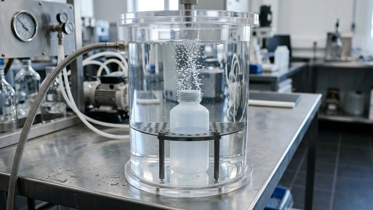
Bubble Leak Test: ASTM F2096, D3078 & Gross Leak Log
A bubble leak test detects gross package leaks in immersion fluid via ASTM F2096 internal pressurization or ASTM D3078 headspace vacuum emission.
Seal Strength Test: Peel Force, Fixtures & Failure Modes
How ASTM F88 seal strength testing controls tail support angle, peel force limits, units, and failure modes across flexible and foil-sealed packaging.

PET vs Glass Bottle Induction Sealing Guide
Compare PET and glass induction sealing on interfacial bond, land treatment, neck thermal limits, liner grade, and operating-window verification.