
Vented Induction Seal Liner vs Hermetic Liner for Off-Gassing Liquids
Compare vented induction seal liners and hermetic induction liners: review off-gassing pressure behavior, ePTFE membrane specs, and leak-testing scope.

Induction cap sealing is used for creating a hermetic seal, while products that are required to breathe benefit from a vented induction liner.
If a product off-gasses, a vented liner is likely needed to allow the container to breathe to prevent bloating and panel distortions, whereas if a product is caustic, the selected induction liner must withstand contact with the product where a universal liner may lack the required properties.
Use the comparison table below to separate hermetic induction liners, vented induction liners, and vented foam liners before running your package trial, alongside our cap liner selection overview.
| Liner System | Construction & Sealing Mechanism | Gas Exchange & Liquid Barrier | Documented Application Scope |
|---|---|---|---|
| Conventional Hermetic Induction Seal Liner | Every induction seal liner includes a layer of foil with a thin layer of polymer on its surface | During induction sealing, the magnetic field heats the foil and melts the polymer to bond to the container rim, creating an airtight hermetic seal that protects against oxygen and moisture transmission | Prevents leaking of liquid products and provides tamper-evidence, unlike a pressure-sensitive liner that adheres by pressure alone |
| Selig AirFoil™ Vented Heat-Induction Liner | Proprietary vented heat-induction liner system available in one-piece, two-piece, and Lift ‘n’ Peel™ liners | Eliminates the distortion of plastic containers by allowing them to breathe while providing a leak-proof closure | Replaces traditional foam, pulp, paper, or foil liners; can be used in conjunction with a Circumvent™ vented foam liner or separately, supplied in roll-stock, tubed or bulk-packed pre-cut discs, or installed into closures |
| GORE® Pulp Induction Liners (Standard Series and High Performance Series) | Weldable induction installation providing tamper-evidence and membrane breathability | Equalizes pressure for gas-scavenging chemicals and off-gassing liquids | Agrochemical bottles up to 20 l, including organic biostimulants |
| Selig Circumvent™ Vented Foam Liner | Vented foam liner offered in flat and groove-backed versions for caps with or without vent holes | Prevents container bloating or paneling that can result from product off-gassing, oxygen scavenging, and changes in temperature or altitude | Reduces the need for fluorination or increased bottle gram weight used to mask bloating or paneling issues |
Why off-gassing and oxygen-scavenging liquids distort hermetic containers
Household, industrial, and commercial products containing bleach, peroxide, or other off-gassing ingredients can cause containers to swell or bloat, while surfactants, solvents, or essential oils can cause containers to collapse or panel due to oxygen scavenging or product migration.
Fluctuations in temperature and altitude during shipping or storage can accelerate unwanted container distortion.
Pressure-sensitive liners adhere when pressure is applied without heat or sealing equipment, do not provide tamper-evidence or prevent leaking of liquid products, and unlike an induction liner which creates an airtight hermetic seal, cannot protect against oxygen and moisture transmission.

Buckman’s Inc. supplies Sodium Hypochlorite Solutions and Hydrochloric Acid formulations that can be up to three times stronger than typical household bleach, and seals its containers with Enercon Super Seal™ induction cap sealers.
After sealing test batches with an Enercon Super Seal™ Jr. and storing bottles upright, on their sides, or upside down for months approaching a full year, Buckman’s Inc. uses a vented liner for Sodium Hypochlorite Solution to allow off-gassing of the product, while Hydrochloric Acid products use a conventional liner designed for chemical resistance.
For general non-vented container resin matching across PE, PP, PET, and glass finishes, review the induction sealing liners guide.
Vented induction liner architecture: microporous ePTFE membranes and cap thread venting
Selig converts standard foam and heat-induction foil liner products to a vented format by integrating breathable materials including expanded polytetrafluoroethylene (ePTFE) membranes.
The microporous structures repel liquids while allowing bi-directional venting to maintain equalized pressure within a closed container.
Selig’s VentShield™ provides a proprietary venting solution for applications that suffer from paneling (oxygen scavenging or transport pressure changes) not solved by standard venting solutions, working with high-viscosity products, creams, lotions, and essential oils.
Selig’s ScentVent™ lets the consumer sample the fragrance of a product in an induction-sealed package without removing or tampering with the seal, while TempVent™ allows pressure to equalize inside packages as the product cools following hot- or warm-filling.
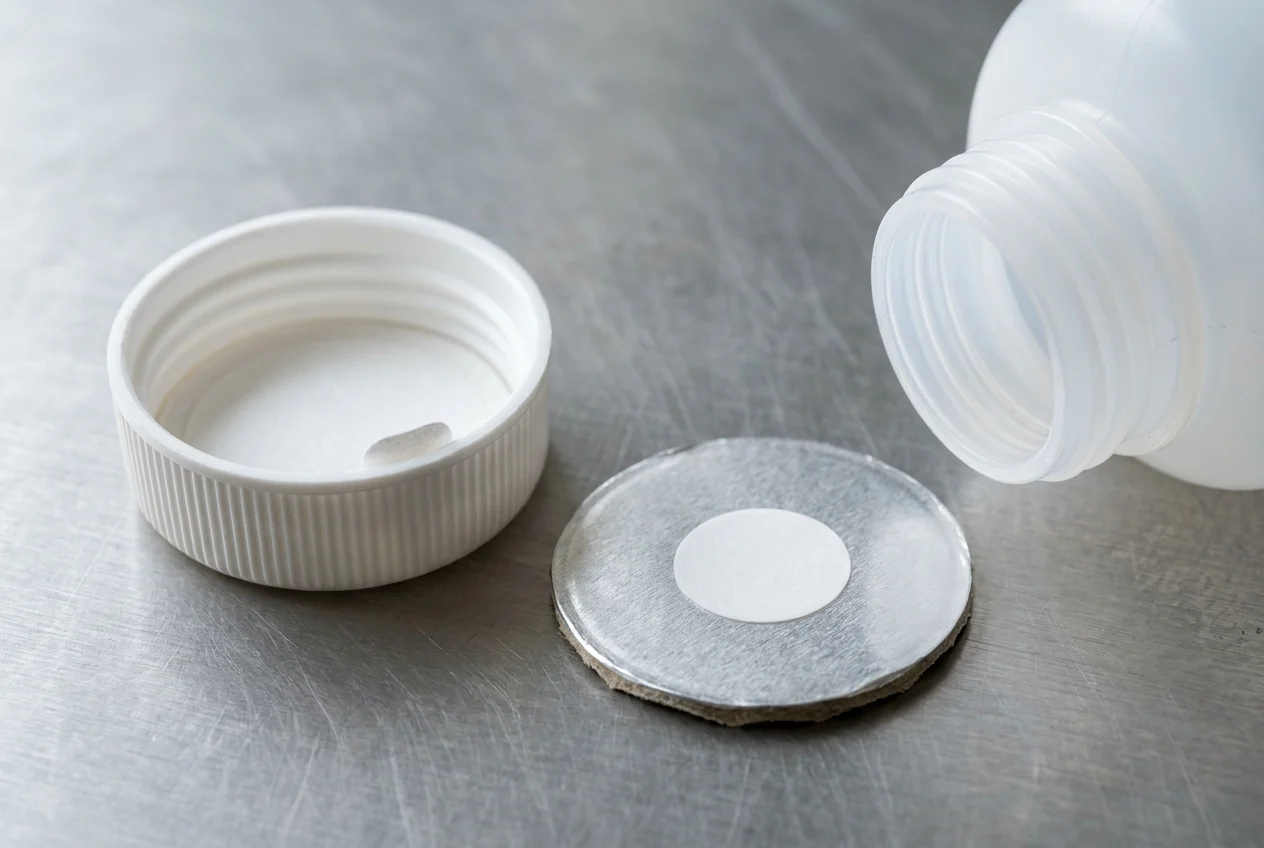
A GORE laminate is constructed of a microporous GORE™ membrane consisting of an expanded polytetrafluoroethylene (ePTFE) layer laminated onto a support material that mechanically stabilizes the membrane and creates the connection during integration.
For GORE Packaging Vents (3FL Cap Liner or Induction Liner) on caps without a hole, gas passes through the microporous ePTFE membrane to an area above the membrane that directs gases to the cap threads while stopping liquid and particles.
A hole in the cap is required when using GORE molded components and two-layer foam liners, but is not required when using a GORE 3FL Cap Liner or Induction Liner.
The microporous structure of the GORE membrane enables gas flow even at the smallest difference in pressure, requiring no initial response pressure to enable gas transport unlike classic valve systems such as mushroom valves.
For the differences between one-piece and wax-backed two-piece separation layers, see our one-piece vs two-piece induction liner comparison.
Hydrophobic vs oleophobic ePTFE membranes and Liquid Entry Pressure (LEP)
Hydrophobic membranes protect high surface tension aqueous liquids like water, whereas Gore’s oleophobic ePTFE membranes protect both aqueous liquids and lower surface tension fluids like oils, soaps, and detergents.
Common end-use applications for GORE hydrophobic venting products are dry products, powders and tablets, pool bleach, pool shock, and products containing bleach and water, disinfectants, hydrogen peroxide, and water.
Common end-use applications for GORE oleophobic vents are household or industrial cleaners, pesticides, liquid fertilizers, scented bleaches, and products containing alcohols, degreasers, detergents, essential oils, fragrance, oils, solvents, and surfactants.
Passing a pressure test with water (WEP test) does not ensure a venting membrane will prevent a chemical formulation from leaking or spilling in real-world conditions because formulations vary in surface tension and viscosity: Gore publishes surface tensions of 73 dyn/cm for water, 22 dyn/cm for ethanol, 64 dyn/cm for glycerol, 78 dyn/cm for hydrogen peroxide (80%), and 25 dyn/cm for mineral spirits.
W.L. Gore & Associates uses the Liquid Entry Pressure (LEP) test beyond the WEP test to identify the pressure required to force specific liquid formulations through the membranes used in GORE® Packaging Vents.
Published specifications for GORE® Pulp Induction Liners and GORE® Foam Liners
Compare the published datasheet specifications for GORE Pulp Induction Liners and GORE Foam Liners in the table below.
| GORE® Liner Series | Membrane / Liner Construction & Thickness | Active Vent Area & Venting Path | Water Entry Pressure (WEP) | Typical Dry Airflow at dp = 12 mbar |
|---|---|---|---|---|
| GORE Pulp Induction Liner CM6B (High Repellency Series) | ePTFE + PE + aluminum + PET + wax + pulp; 1.0 mm thickness; lot-level traceability | 0.6 mm venting hole diameter; cap thread venting (venting through a hole in the cap also possible) | > 0.5 bar | 0.17 l/h for a 52.3 mm roll slit width (disc diameters up to 46.3 mm) and 0.18 l/h for a 69.9 mm roll slit width (disc diameters up to 63.9 mm) |
| GORE Pulp Induction Liner CM6C (High Repellency Series) | ePTFE + PE + aluminum + PET + wax + pulp; 1.0 mm thickness; lot-level traceability | 0.6 mm venting hole diameter; cap thread venting (venting through a hole in the cap also possible) | > 0.5 bar | 0.29 l/h for a 52.3 mm roll slit width (disc diameters up to 46.3 mm) and 0.42 l/h for a 69.9 mm roll slit width (disc diameters up to 63.9 mm) |
| GORE Pulp Induction Liner CM8C (High Airflow Series) | ePTFE + PE + aluminum + PET + wax + pulp; 1.0 mm thickness; lot-level traceability | 2.0 mm venting hole diameter; cap thread venting (venting through a hole in the cap also possible) | > 0.3 bar | 1.93 l/h for a 52.3 mm roll slit width (disc diameters up to 46.3 mm) and 5.93 l/h for a 69.9 mm roll slit width (disc diameters up to 63.9 mm) |
| GORE Foam Liner Standard Series (3FL-323G/324G, Order Numbers 323G and 324G) | ePTFE / PE foam; 1.1 mm and 1.9 mm thicknesses | Full-surface active vent area | > 1.4 bar | 0.7 l/h/cm2 |
| GORE Foam Liner High Performance Series (3FL-383G/384G, Order Numbers 383G and 384G) | ePTFE / PE foam; 1.1 mm and 1.9 mm thicknesses | Full-surface active vent area | > 1.4 bar | 1.8 l/h/cm2 |
Qualification constraints: wet airflow, bottle orientation, closure torque, and hazmat transport
The airflow value in liters per hour (l/h) in Gore product information is a dry measured value where the vent has not been dampened by liquid in advance; direct contact with a liquid can significantly change remaining airflow, so an on-site application test must be performed rather than choosing a vent on dry airflow alone.
If liquid product covers the membrane surface of a GORE® Packaging Vent when a container is on its side or upside down, gas exchange cannot take place because the gas in the container must be able to sit directly on the active surface of the membrane.
When GORE Packaging Vents Liners are used, closures must be installed at the recommended torque so the liner is not compressed too hard (which can reduce venting performance), the liner should preferably be mounted in the cap with an undercut rather than glued, and any required venting hole in the cap should meet the recommended ø 2 mm dimension and not be blocked.
Under 49 CFR § 173.24(g), venting of packagings to reduce internal pressure developed by the evolution of gas from the contents is permitted only when transportation by aircraft is not involved (except cryogenic liquids under § 173.320(c) and solid carbon dioxide/dry ice), the evolved gases are not poisonous, likely to create a flammable mixture with air, or an asphyxiant, and the packaging precludes unintentional release of hazardous materials.
Under 49 CFR § 173.24(e)(3)(ii), the maximum rate of permeation of hazardous lading through or into plastic packagings or receptacles may not exceed 0.5 percent for Division 6.1 materials (§ 173.132) and 2.0 percent for other hazardous materials when tested at no lower than 18 °C (64 °F) for 180 days (Test Method 1), 50 °C (122 °F) for 28 days (Test Method 2), or 60 °C (140 °F) for 14 days (Test Method 3).
Container closure integrity testing (CCIT) boundaries for vented vs hermetic liners
ASTM F2338-24 (Standard Test Method for Nondestructive Detection of Leaks in Packages by Vacuum Decay Method) detects package leaks by measuring the rise in pressure (vacuum loss) in an enclosed evacuated test chamber containing the test package, resulting from leakage of headspace gases and/or volatilization of liquid contents.
Clause 5.2 of ASTM F2338-24 states that it is important to physically mask or block off any package porous barrier surface during the vacuum decay test to prevent rapid loss of chamber vacuum resulting primarily from gas migration through the porous surface.
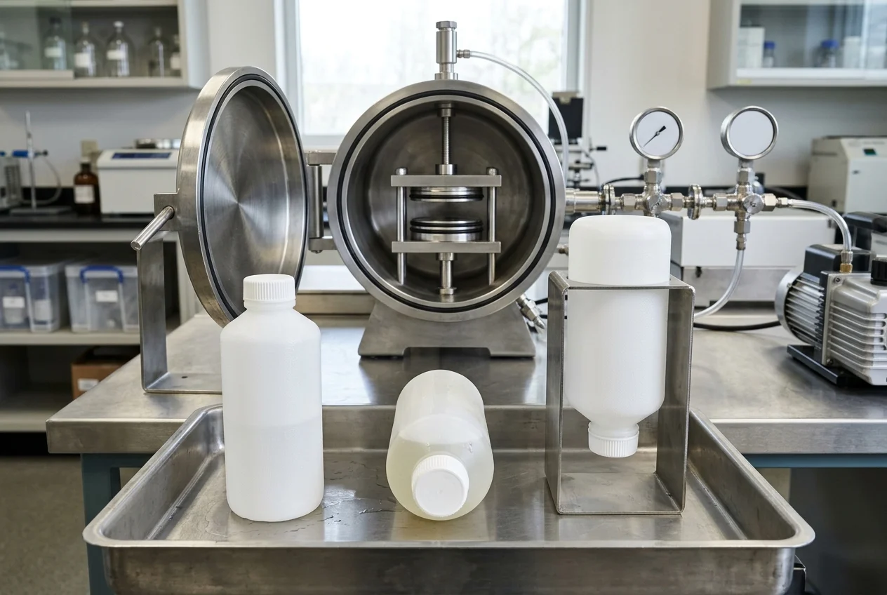
Under ASTM F2338-24 Clause 1.2.2, trays sealed with porous barrier lidding material tested at a Target Vacuum of –4·E4 Pa (–400 mbar) can detect hole or crack defects in the wall of the tray/cup of at least 100 μm in diameter and channel defects in the seal area made using wires of 125 μm in diameter, with a test sensitivity of approximately E-2 Pa·m3·s-1.
Under ASTM F2338-24 Clauses 1.2.3 and 1.2.4, rigid nonporous packages can detect hole defects of at least 5 μm in diameter; under Clause 1.2.3, plastic bottles with screw caps tested at a target vacuum of –5·E4 Pa (–500 mbar) have a test sensitivity of approximately E-3.4 Pa·m3·s-1.
Under ASTM F2338-24 Clause 1.3, vacuum decay test results are qualitative (Accept/Reject), with acceptance criteria established by comparing quantitative baseline vacuum decay measurements from control, non-leaking packages to measurements from leaking packages and simulated leaks using a calibrated gas flow meter.
PTI’s VeriPac vacuum decay systems utilize ASTM F2338 (recognized by the FDA as a consensus standard and referenced in USP <1207> and ISO 11607), where test sensitivity is a function of package design, package test fixture, and critical test parameters of time and pressure.
PTI’s VeriPac Delta benchtop system combines vacuum decay and pressure decay technologies, providing vacuum decay detection down to 5 microns and pressure decay detection down to 10 microns with a rapid test time of 10 seconds.
Compare the scope boundaries of common leak and seal-strength standards in the table below, and continue to our closure integrity testing guide and seal integrity testing hub for line setup details.
| Standard / Method | Documented Package & Defect Scope | Boundary for Vented or Liquid Chemical Containers |
|---|---|---|
| ASTM F2338-24 Vacuum Decay | Rigid nonporous packages detect hole defects of at least 5 μm in diameter; plastic bottles with screw caps at a target vacuum of –5·E4 Pa (–500 mbar) have a test sensitivity of approximately E-3.4 Pa·m3·s-1 | Clause 5.2 states that it is important to physically mask or block off any package porous barrier surface during the vacuum decay test to prevent rapid loss of chamber vacuum resulting primarily from gas migration through the porous surface |
| ASTM D3078-02(2021)e1 Bubble Emission | Covers gross leaks in flexible packaging containing a headspace gas, with test sensitivity limited to 1 × 10⁻⁵ atm cm3/s (1 × 10⁻⁶ Pa m3/s) or even less sensitive | Clause 1.2 warns that viscoelastic effects, entrapped air, or product forced by positive pouch pressure may plug small leaks |
| ASTM D5094/D5094M-24 Gross Liquid Leakage | Covers qualitative determination of gross leaks in rigid and semi-rigid containers up to 4 L via Test Method A (Shipping Container Vibration and Storage Test) and Test Method B (Shipping Container Vibration and Vacuum Chamber Test) | Clause 1.1 cautions that these test methods may not be suitable for containers intended for transport of hazardous materials |
| ASTM F88/F88M-23 Seal Strength | Measures the force required to separate a test strip of material containing a seal using Technique A (Unsupported), Technique B (Supported 90° by hand), or Technique C (Supported 180°) | Clause 1.5 states that it differs from Test Method F2824, which separates an entire lid/membrane from a rigid or semi-rigid round container |
| USP <1207> (DOI 10.31003/USPNF_M99926_01_01) | Provides guidance on the integrity assurance of nonporous packages intended for sterile pharmaceutical products across three subchapters: <1207.1>, <1207.2>, and <1207.3> | Scoped to nonporous packages intended for sterile pharmaceutical products |
In Enercon’s demonstration sealing two LDPE bottles at 100% power through a deep tunnel sealing head—one with an incompatible liner and one with a compatible universal liner—both seals appear identical on visual inspection after cooling, showing that visual inspection alone cannot confirm liner compatibility because the incompatible liner pops off with a slight touch.
Vented vs hermetic liner qualification record
Record the formulation, membrane construction, closure mounting, and leak-test protocol together before approving a vented or hermetic induction liner specification:
- Liquid formulation identity, off-gassing or oxygen-scavenging behavior, and surface tension: ______
- Selected liner construction (hermetic induction liner, vented induction liner, or vented foam liner) and lot trace: ______
- Membrane type (hydrophobic vs oleophobic ePTFE) and required Water Entry Pressure (WEP) or Liquid Entry Pressure (LEP) test result: ______
- Container resin, mouth diameter, closure design (undercut vs glued mounting, thread venting vs cap hole dimension), and application torque: ______
- Orientation storage test conditions (upright, side, and inverted) and residual airflow check after liquid contact: ______
- Transport mode and regulatory qualification basis: ______
- Container closure integrity test method, porous-barrier masking fixture, and peel-strength verification: ______
Common questions
When does a liquid require a vented induction liner instead of a hermetic liner?
If a product off-gasses, a vented liner is likely needed to allow the container to breathe to prevent bloating and panel distortions. Household, industrial, and commercial products containing bleach, peroxide, or other off-gassing ingredients can cause containers to swell or bloat, while surfactants, solvents, or essential oils can cause containers to collapse or panel due to oxygen scavenging or product migration.
Does a vented induction liner require a hole drilled in the cap?
A hole in the cap is required when using GORE molded components and two-layer foam liners, but is not required when using a GORE 3FL Cap Liner or Induction Liner. For GORE Packaging Vents (3FL Cap Liner or Induction Liner) on caps without a hole, gas passes through the microporous ePTFE membrane to an area above the membrane that directs gases to the cap threads while stopping liquid and particles.
Why must porous vent membranes be masked during ASTM F2338 vacuum decay testing?
Clause 5.2 of ASTM F2338-24 states that it is important to physically mask or block off any package porous barrier surface during the vacuum decay test to prevent rapid loss of chamber vacuum resulting primarily from gas migration through the porous surface.
Are vented packages permitted on aircraft under 49 CFR § 173.24(g)?
Under 49 CFR § 173.24(g), venting of packagings to reduce internal pressure developed by the evolution of gas from the contents is permitted only when transportation by aircraft is not involved (except cryogenic liquids under § 173.320(c) and solid carbon dioxide/dry ice), the evolved gases are not poisonous, likely to create a flammable mixture with air, or an asphyxiant, and the packaging precludes unintentional release of hazardous materials.
Sources
- Selig Group — Venting Technologies
- Selig Group — Circumvent Venting Technology
- Selig Group — AirFoil Venting Technology
- Enercon Industries — Liner Options for Sealing Capped Containers, Bottles, & Jars
- Enercon Industries — Induction Sealing with Vented Liners Prevent Leaks & Maintain Package Integrity
- Enercon Industries — Induction Sealing Ensures Corrosive Chemicals Arrive Leak Free
- Enercon Industries — Troubleshooting Induction Seals: Container & Liner Material
- W.L. Gore & Associates — FAQ for GORE Packaging Vents
- W.L. Gore & Associates — GORE Packaging Vents: Liners for Pressure Equalization in Sealed Packaging
- W.L. Gore & Associates — Data Sheet: GORE Packaging Vents for Chemicals and Cleaners
- W.L. Gore & Associates — Technical Information: Liquid Entry Pressure Testing with GORE Packaging Vents
- Electronic Code of Federal Regulations — 49 CFR § 173.24 General Requirements for Packagings and Packages
- ASTM International — ASTM F2338-24 Standard Test Method for Nondestructive Detection of Leaks in Packages by Vacuum Decay Method
- PTI Packaging Technologies & Inspection — Vacuum Decay Leak Detection (ASTM F2338)
- ASTM International — ASTM D3078-02(2021)e1 Standard Test Method for Determination of Leaks in Flexible Packaging by Bubble Emission
- ASTM International — ASTM D5094/D5094M-24 Standard Test Methods for Gross Leakage of Liquids from Containers with Threaded or Lug-Style Closures
- ASTM International — ASTM F88/F88M-23 Standard Test Method for Seal Strength of Flexible Barrier Materials
- United States Pharmacopeia — USP <1207> Package Integrity Evaluation—Sterile Products
More about Cap & Liner Selection
One-piece and two-piece wax-backed or polymer-bonded foil innerseals, container resin compatibility (PE, PP, PET, PVC, glass), and ROPP vs. cork closures.
Related Articles
Induction Seal Application Torque Window: Liner Compression vs Coil Power
Set up your induction seal application torque trial with starting guidelines, removal-torque checks, contact inspection and a blank package record.
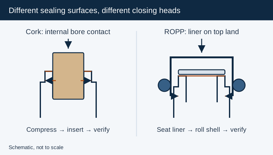
Cork vs Screw Cap: What Changes in the Bottling and Closing Process?
Compare still-wine cork insertion and ROPP screw capping by bottle finish, closing action, headspace control, liner and release tests.
Induction Foil Seal Adhesion Failure and Overheating Troubleshooting Guide
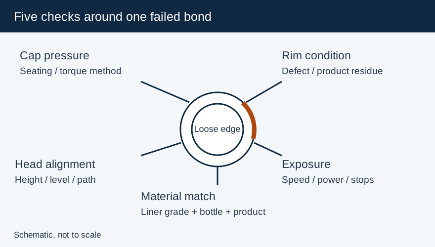
Use five checks—cap pressure, rim condition, coil alignment, conveyor exposure and material match—to isolate foil adhesion failure and overheating.