
Hot-Fill vs Cold-Fill Induction Sealing: Foil Heating Window and Headspace Pressure
Compare hot-fill and cold-fill induction sealing, then qualify the heating window, neck fit and cooled-pack integrity before transferring a line recipe.
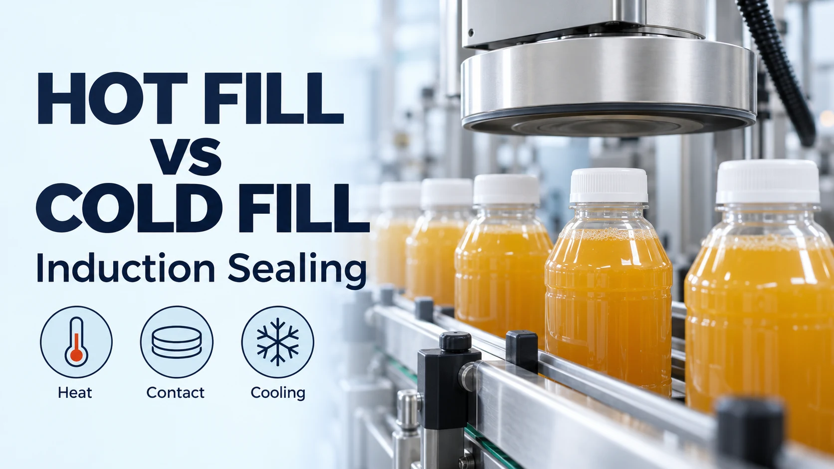
For induction sealing, hot fill usually needs less energy than cold fill in an otherwise comparable package. Verify the operating window before transferring a recipe between them. Fill temperature changes how the package removes heat from the liner; cooling also changes the loads on the closed bottle. A shared recipe is suitable only where the qualified hot-fill and cold-fill windows overlap.
The changeover decision therefore depends on three separate quantities: product temperature at the sealer, local foil and seal-layer temperature, and headspace pressure during cooling. Use the comparison below to plan a filled-pack trial, alongside the equipment and application guidance in induction sealing machines.
| Decision variable | Hot fill | Cold fill | Changeover check |
|---|---|---|---|
| Starting thermal condition | Product and package enter the process warm | Cooler contents can remove more heat from the liner region | Record product temperature at induction entry and keep fill level comparable |
| Heating exposure | Often needs less induction energy for the same package | Normally needs more energy than comparable hot fill | Establish acceptable power and speed combinations on filled packs |
| Recipe-transfer risk | A cold-fill recipe can overheat the liner or sealing land | A hot-fill recipe can leave an inadequate bond | Inspect both the low- and high-exposure boundaries after cooling |
| Neck and closure fit | Thermal expansion can affect fit, torque readings and package height | Fit must meet the package specification at its operating temperature | Check seating, liner contact and actual head clearance |
| Cooling load | Volume changes can create vacuum in conventional hot-fill packs | Pressure still depends on the contents and subsequent temperature history | Evaluate the complete filling, closing and cooling sequence |
| Acceptance | Bond, opening, leakage and dimensional requirements apply after the specified conditioning | The same acceptance categories apply to the qualified cold-fill configuration | Use agreed methods and retain the sample conditions with each result |
Selig’s PHT manual (2020), page 17, describes the fill-temperature and fill-level heat-sink effects. Its operating-window procedure on page 56 bases the decision on actual production conditions and cooled samples.
Product temperature and foil temperature do different jobs
Measure the product temperature at induction entry; use the liner grade and filled-pack trial to establish the heating exposure. The filling-machine temperature alone can miss changes caused by the time between filling, capping and sealing.
Induction energy heats the aluminum foil. Heat then passes into the bottle-facing seal layer and the container’s sealing land—the narrow surface around the mouth that contacts the liner. Sufficient exposure activates the seal layer; the bond develops as the assembly cools. The bulk liquid temperature is a starting condition, while the local foil and seal-layer temperatures change during this short heating and cooling cycle.
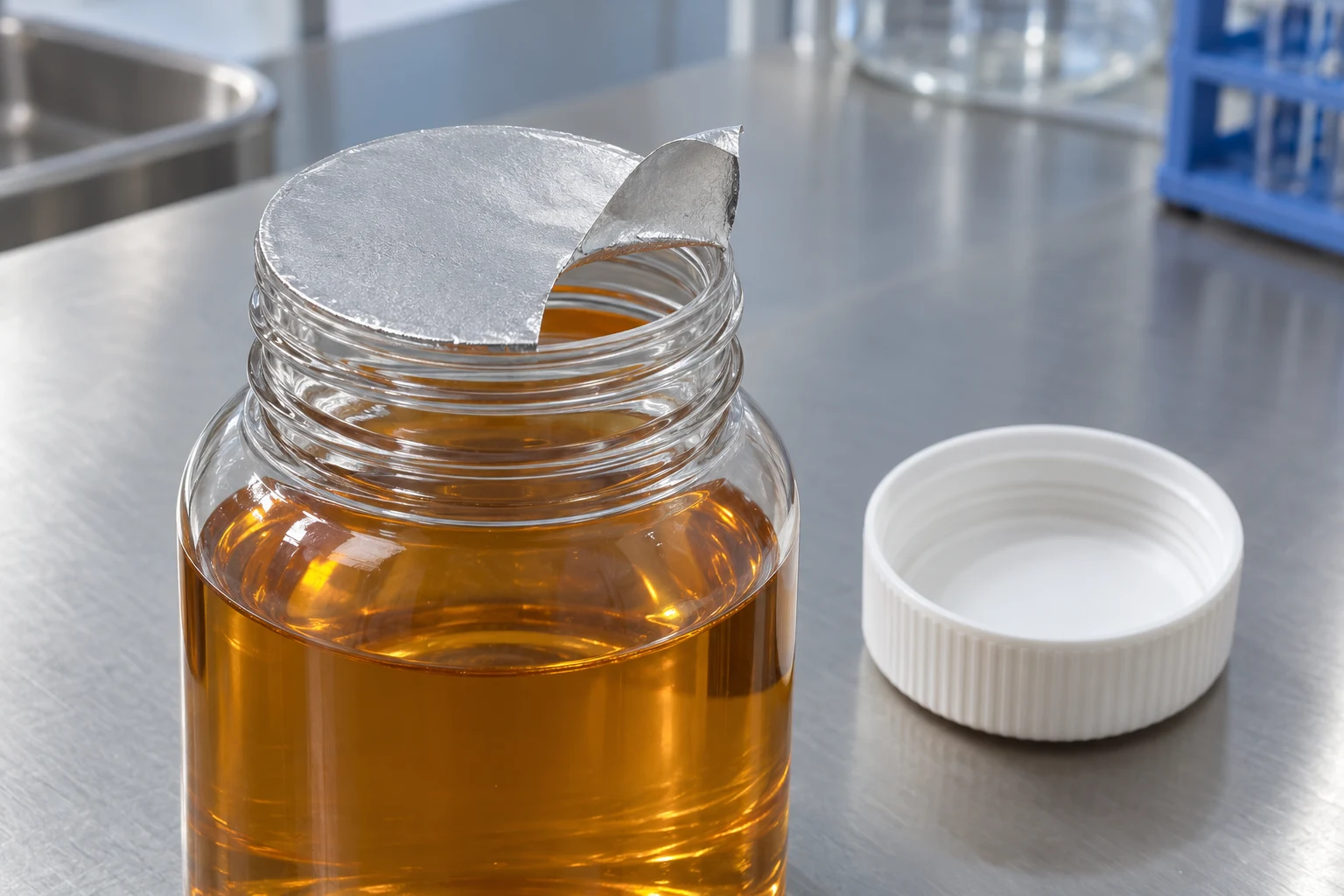
The container absorbs heat from the liner. Selig identifies both fill temperature and fill level as influences on this heat-sink behavior. That is why an empty-bottle setup can give a misleading result for a filled production pack, and why a temperature comparison should retain the intended fill level. Product touching the liner or contaminating the land adds another variable; correct the fill and handling condition before interpreting the power trial.
Keep cap contact pressure separate from headspace pressure. The closure mechanically holds the liner against the rim during sealing. Headspace pressure acts within the closed package and evolves with its subsequent process history. Good control of one does not establish the other.
Find the acceptable foil-heating window
Establish the lower and upper acceptance boundaries with the actual bottle, closure, liner and contents. Fix uneven contact before increasing power. In Selig’s heat-sink explanation, poor contact can leave part of the liner inadequately cooled and locally overheated, even while the seal as a whole is weak.
Start with the approved cap/liner assembly and confirm full seating, a clean and even sealing land, stable conveyor speed, and the coil position and clearance specified for that setup. Check application torque across the capping heads. For hot fill, make these checks at the relevant production temperature because package dimensions can change.
Explore exposure by changing one controlled setting at a time within the equipment and package suppliers’ trial procedure. Identify each sample with its settings and entry temperature, follow the required process sequence, and allow it to reach the agreed inspection condition before opening or testing it.
| Trial boundary | Evidence to examine | Response |
|---|---|---|
| Insufficient exposure | Incomplete rim bond, unacceptable opening behavior or leakage | Check material compatibility and contact; then investigate additional exposure |
| Acceptable window | Required full-rim bond, opening and leak performance, with acceptable package geometry | Confirm the candidate setting across the intended temperature and process range |
| Excessive exposure | Liner distortion, overheating damage or unacceptable change to the sealing land or closure | Reduce exposure and investigate contact uniformity and package heat resistance |
The usable window includes all required package criteria. A seal that bonds firmly but opens poorly, or a bottle that distorts during cooling, still needs correction. Use the adhesion and overheating guide when weak areas and thermal damage occur together.
Keep a shared hot/cold recipe only when it passes both qualifications with room for normal process variation. Where the acceptable ranges do not overlap, use separate qualified recipes or revise the package/process combination. Confirm the selected combination after the exploratory trial, including the intended temperature limits and relevant start, stop and restart conditions.
Headspace pressure changes as the bottle cools
Assess the cooled package as well as the seal immediately after the induction station. Headspace is the gas space above the liquid. As a conventional hot-filled package cools, changes in gas temperature, liquid volume and vapor condensation can reduce internal pressure. Bottle deformation and any gas-dosing step also affect the pressure history.
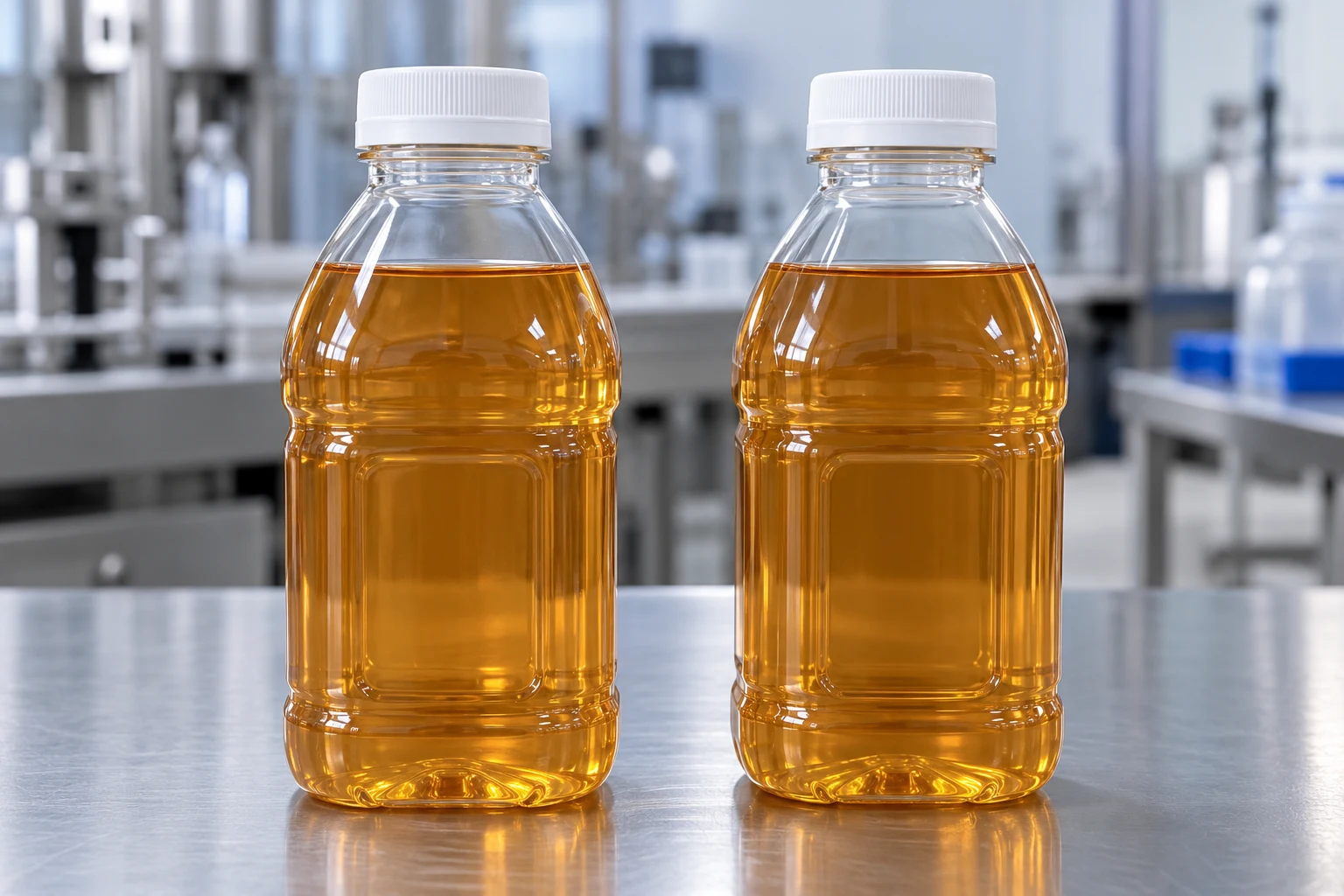
Sidel’s Hot Fill technical material describes vacuum panels in traditional heat-resistant PET bottles as a way to accommodate volume changes between hot and cold conditions. This makes the bottle’s response part of the qualification: examine sidewall shape, neck geometry, closure fit and seal integrity after the specified cooling sequence.
Hot filling can also use a deliberately managed pressure history. Krones’ NitroHotfill brochure describes nitrogen dosing after filling, followed by cooling that reduces the resulting internal pressure. The distinction matters when specifying the trial: record the actual gas-dosing and cooling process so the pressure assessment matches the package being sealed.
Treat cooling pressure as a package load to evaluate. Set any pressure-measurement method and acceptance criteria from the package design, alongside the required leakage and opening tests. Fill temperature alone is insufficient to calculate that load because headspace volume, gas composition, product contraction and bottle compliance also matter.
Retain the process owner’s required inversion, holding and cooling sequence. Selig’s manual emphasizes allowing the seal to cool and avoiding rough handling while the bond develops. Agree inspection timing and handling with the package and process owners, then use the closure integrity testing guide to select the appropriate evidence for leakage and opening performance.
Check hot neck fit separately from liner compatibility
Qualify both the container neck and the liner grade for the fill process. A suitable heat-seal layer still needs a stable sealing land and a closure that applies even pressure.
Selig’s manual, page 29, explains that hot-fill neck expansion can prevent a cap from tightening fully while producing misleading application-torque readings. It also notes that changes in package height can affect the gap below the induction head. Check actual cap seating, thread engagement, liner flatness and clearance together with torque.
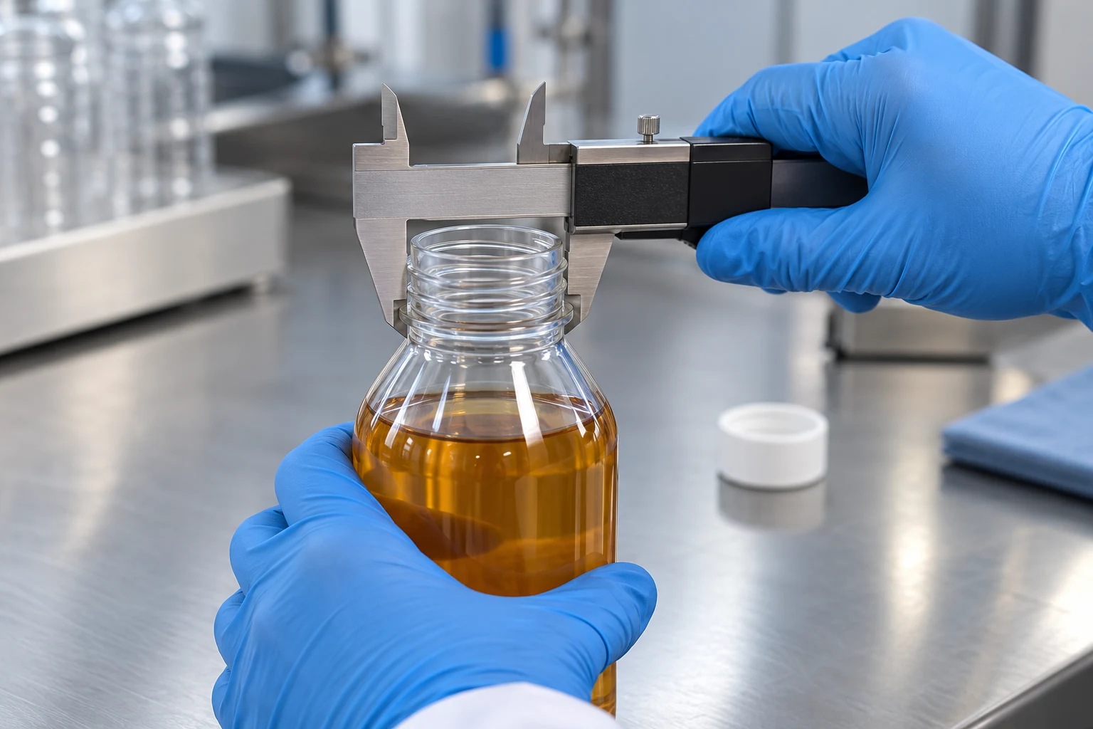
For PET, neck crystallization is one documented way of improving resistance to deformation during hot filling and capping; Nissei ASB describes that purpose in its Neck Crystallizer technical material. Select the container’s qualified neck design and temperature range for the application, then verify its dimensional behavior through the actual process.
A cold-fill induction liner should be specified by grade, compatible container surface, contents and required opening behavior. When moving to hot fill, reassess the grade’s temperature suitability and any backing-release behavior as well as the seal. Use the liner selection guide for compatibility and the one-piece versus two-piece comparison for the layer and release requirements.
Temperature-changeover trial checklist
Keep one record that connects each sample’s thermal and mechanical conditions to its cooled-pack result. Agree nominal and limiting production conditions with the package owner before running the comparison.
| Record group | Capture for each trial condition |
|---|---|
| Product and temperature | Product identity; temperature at filling and at induction entry; intended operating range |
| Package identity | Container resin/grade and neck drawing; hot-fill qualification; closure specification; liner grade and construction; component lots |
| Fill and timing | Fill volume/level and headspace; fill-to-cap and cap-to-induction delay; required inversion, hold and cooling sequence; gas dosing if used |
| Mechanical setup | Cap application torque by head; seating and contact observations; coil configuration, alignment and measured clearance |
| Heating exposure | Conveyor linear speed and power setting, associated with the actual machine and coil |
| Conditioning and results | Time and thermal condition at inspection; rim bond, opening and leakage results; neck/sidewall deformation; pressure measurements where required |
First compare hot and cold conditions with the intended package components and fill level. Establish each acceptable window, then confirm the proposed recipe or recipes across the agreed production range. Retain separate sample results for each condition so an acceptable average cannot conceal a failing temperature limit.
For the next technical review, assemble the fill temperature, bottle-neck material, liner structure and cap application torque, together with the completed trial record. The machine selection guide helps connect that package evidence to equipment selection, while the capping and sealing integration guide covers timing and conveying between stations.
Technical references
- Selig Group, PHT manual (2020): pages 13 and 16–17 for heating, cooling and heat-sink behavior; page 29 for neck, closure, clearance and product considerations; page 56 for operating-window trials.
- Sidel, Hot Fill: “Staying ahead with innovative packaging,” on vacuum panels and volume changes in heat-resistant PET bottles.
- Krones, NitroHotfill brochure: pages 3–4, on nitrogen dosing after filling and subsequent cooling.
- Nissei ASB, Neck Crystallizer: the application description for preventing neck deformation during hot filling and capping.
More about Induction Sealing Machines
Electromagnetic induction cap sealers, flat vs. tunnel sealing coils, kW power-to-line-speed matching, capping head integration, and troubleshooting.
Related Articles
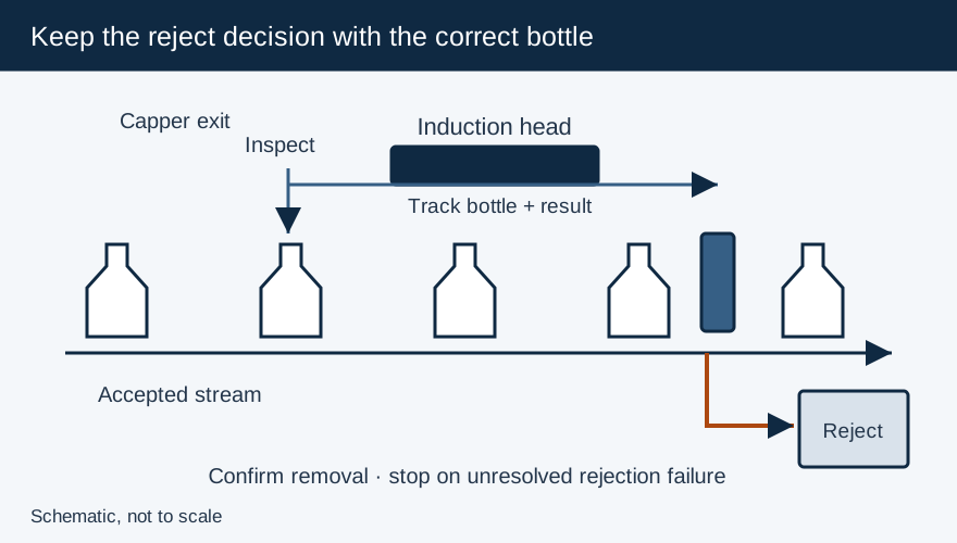
Capping and Induction Sealing: Line Interfaces and Rejection
Specify capper-to-sealer transfer, conveyor stop protection, inspection signals and confirmed rejection for an induction sealing line.
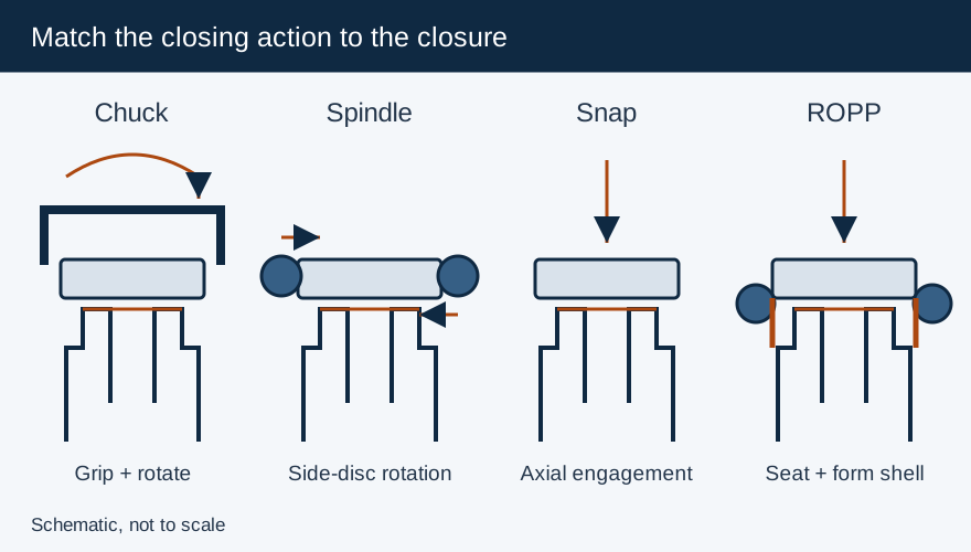
Capping Machines Explained: Match the Cap, Container and Closing Process
Compare chuck, spindle, snap and ROPP closing mechanisms, then specify container support, torque checks and the capper-to-sealer interface.
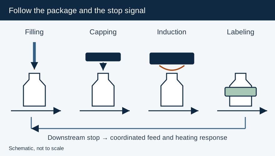
Integrating Filling, Capping and Labeling: Define Transfer, Timing and Reject Interfaces
Define conveyor, rate and reject interfaces between filling, capping, induction sealing and labeling, including safe stop and restart behavior.